//! # Image Processing
//!
//! This module includes image-processing functions.
//! # Image Filtering
//!
//! Functions and classes described in this section are used to perform various linear or non-linear
//! filtering operations on 2D images (represented as Mat's). It means that for each pixel location
//!  in the source image (normally, rectangular), its neighborhood is considered and used to
//! compute the response. In case of a linear filter, it is a weighted sum of pixel values. In case of
//! morphological operations, it is the minimum or maximum values, and so on. The computed response is
//! stored in the destination image at the same location . It means that the output image
//! will be of the same size as the input image. Normally, the functions support multi-channel arrays,
//! in which case every channel is processed independently. Therefore, the output image will also have
//! the same number of channels as the input one.
//!
//! Another common feature of the functions and classes described in this section is that, unlike
//! simple arithmetic functions, they need to extrapolate values of some non-existing pixels. For
//! example, if you want to smooth an image using a Gaussian  filter, then, when
//! processing the left-most pixels in each row, you need pixels to the left of them, that is, outside
//! of the image. You can let these pixels be the same as the left-most image pixels ("replicated
//! border" extrapolation method), or assume that all the non-existing pixels are zeros ("constant
//! border" extrapolation method), and so on. OpenCV enables you to specify the extrapolation method.
//! For details, see #BorderTypes
//!
//! @anchor filter_depths
//! ### Depth combinations
//! Input depth (src.depth()) | Output depth (ddepth)
//! --------------------------|----------------------
//! CV_8U | -1/CV_16S/CV_32F/CV_64F
//! CV_16U/CV_16S | -1/CV_32F/CV_64F
//! CV_32F | -1/CV_32F/CV_64F
//! CV_64F | -1/CV_64F
//!
//!
//! Note: when ddepth=-1, the output image will have the same depth as the source.
//!
//! # Geometric Image Transformations
//!
//! The functions in this section perform various geometrical transformations of 2D images. They do not
//! change the image content but deform the pixel grid and map this deformed grid to the destination
//! image. In fact, to avoid sampling artifacts, the mapping is done in the reverse order, from
//! destination to the source. That is, for each pixel  of the destination image, the
//! functions compute coordinates of the corresponding "donor" pixel in the source image and copy the
//! pixel value:
//!
//! 
//!
//! In case when you specify the forward mapping , the OpenCV functions first compute the corresponding inverse mapping
//!  and then use the above formula.
//!
//! The actual implementations of the geometrical transformations, from the most generic remap and to
//! the simplest and the fastest resize, need to solve two main problems with the above formula:
//!
//! - Extrapolation of non-existing pixels. Similarly to the filtering functions described in the
//! previous section, for some , either one of , or , or both
//! of them may fall outside of the image. In this case, an extrapolation method needs to be used.
//! OpenCV provides the same selection of extrapolation methods as in the filtering functions. In
//! addition, it provides the method #BORDER_TRANSPARENT. This means that the corresponding pixels in
//! the destination image will not be modified at all.
//!
//! - Interpolation of pixel values. Usually  and  are floating-point
//! numbers. This means that  can be either an affine or perspective
//! transformation, or radial lens distortion correction, and so on. So, a pixel value at fractional
//! coordinates needs to be retrieved. In the simplest case, the coordinates can be just rounded to the
//! nearest integer coordinates and the corresponding pixel can be used. This is called a
//! nearest-neighbor interpolation. However, a better result can be achieved by using more
//! sophisticated [interpolation methods](http://en.wikipedia.org/wiki/Multivariate_interpolation) ,
//! where a polynomial function is fit into some neighborhood of the computed pixel , and then the value of the polynomial at  is taken as the
//! interpolated pixel value. In OpenCV, you can choose between several interpolation methods. See
//! resize for details.
//!
//!
//! Note: The geometrical transformations do not work with `CV_8S` or `CV_32S` images.
//!
//! # Miscellaneous Image Transformations
//! # Drawing Functions
//!
//! Drawing functions work with matrices/images of arbitrary depth. The boundaries of the shapes can be
//! rendered with antialiasing (implemented only for 8-bit images for now). All the functions include
//! the parameter color that uses an RGB value (that may be constructed with the Scalar constructor )
//! for color images and brightness for grayscale images. For color images, the channel ordering is
//! normally *Blue, Green, Red*. This is what imshow, imread, and imwrite expect. So, if you form a
//! color using the Scalar constructor, it should look like:
//!
//! 
//!
//! If you are using your own image rendering and I/O functions, you can use any channel ordering. The
//! drawing functions process each channel independently and do not depend on the channel order or even
//! on the used color space. The whole image can be converted from BGR to RGB or to a different color
//! space using cvtColor .
//!
//! If a drawn figure is partially or completely outside the image, the drawing functions clip it. Also,
//! many drawing functions can handle pixel coordinates specified with sub-pixel accuracy. This means
//! that the coordinates can be passed as fixed-point numbers encoded as integers. The number of
//! fractional bits is specified by the shift parameter and the real point coordinates are calculated as
//!  . This feature is
//! especially effective when rendering antialiased shapes.
//!
//!
//! Note: The functions do not support alpha-transparency when the target image is 4-channel. In this
//! case, the color[3] is simply copied to the repainted pixels. Thus, if you want to paint
//! semi-transparent shapes, you can paint them in a separate buffer and then blend it with the main
//! image.
//!
//! # Color Space Conversions
//! # ColorMaps in OpenCV
//!
//! The human perception isn't built for observing fine changes in grayscale images. Human eyes are more
//! sensitive to observing changes between colors, so you often need to recolor your grayscale images to
//! get a clue about them. OpenCV now comes with various colormaps to enhance the visualization in your
//! computer vision application.
//!
//! In OpenCV you only need applyColorMap to apply a colormap on a given image. The following sample
//! code reads the path to an image from command line, applies a Jet colormap on it and shows the
//! result:
//!
//! @include snippets/imgproc_applyColorMap.cpp
//!
//! @see #ColormapTypes
//!
//! # Planar Subdivision
//!
//! The Subdiv2D class described in this section is used to perform various planar subdivision on
//! a set of 2D points (represented as vector of Point2f). OpenCV subdivides a plane into triangles
//! using the Delaunay's algorithm, which corresponds to the dual graph of the Voronoi diagram.
//! In the figure below, the Delaunay's triangulation is marked with black lines and the Voronoi
//! diagram with red lines.
//!
//! 
//!
//! The subdivisions can be used for the 3D piece-wise transformation of a plane, morphing, fast
//! location of points on the plane, building special graphs (such as NNG,RNG), and so forth.
//!
//! # Histograms
//! # Structural Analysis and Shape Descriptors
//! # Motion Analysis and Object Tracking
//! # Feature Detection
//! # Object Detection
//! # C API
//! # Hardware Acceleration Layer
//! # Functions
//! # Interface
use std::os::raw::{c_char, c_void};
use libc::{ptrdiff_t, size_t};
use crate::{Error, Result, core, sys, types};
use crate::core::{_InputArray, _OutputArray};
pub const ADAPTIVE_THRESH_GAUSSIAN_C: i32 = 1;
pub const ADAPTIVE_THRESH_MEAN_C: i32 = 0;
/// BBDT algorithm for 8-way connectivity, SAUF algorithm for 4-way connectivity
pub const CCL_DEFAULT: i32 = -1;
/// BBDT algorithm for 8-way connectivity, SAUF algorithm for 4-way connectivity
pub const CCL_GRANA: i32 = 1;
/// SAUF algorithm for 8-way connectivity, SAUF algorithm for 4-way connectivity
pub const CCL_WU: i32 = 0;
/// The total area (in pixels) of the connected component
pub const CC_STAT_AREA: i32 = 4;
/// The vertical size of the bounding box
pub const CC_STAT_HEIGHT: i32 = 3;
/// The leftmost (x) coordinate which is the inclusive start of the bounding
pub const CC_STAT_LEFT: i32 = 0;
pub const CC_STAT_MAX: i32 = 5;
/// The topmost (y) coordinate which is the inclusive start of the bounding
pub const CC_STAT_TOP: i32 = 1;
/// The horizontal size of the bounding box
pub const CC_STAT_WIDTH: i32 = 2;
pub const CHAIN_APPROX_NONE: i32 = 1;
pub const CHAIN_APPROX_SIMPLE: i32 = 2;
pub const CHAIN_APPROX_TC89_KCOS: i32 = 4;
pub const CHAIN_APPROX_TC89_L1: i32 = 3;
/// 
pub const COLORMAP_AUTUMN: i32 = 0;
/// 
pub const COLORMAP_BONE: i32 = 1;
/// 
pub const COLORMAP_CIVIDIS: i32 = 17;
/// 
pub const COLORMAP_COOL: i32 = 8;
/// 
pub const COLORMAP_HOT: i32 = 11;
/// 
pub const COLORMAP_HSV: i32 = 9;
/// 
pub const COLORMAP_INFERNO: i32 = 14;
/// 
pub const COLORMAP_JET: i32 = 2;
/// 
pub const COLORMAP_MAGMA: i32 = 13;
/// 
pub const COLORMAP_OCEAN: i32 = 5;
/// 
pub const COLORMAP_PARULA: i32 = 12;
/// 
pub const COLORMAP_PINK: i32 = 10;
/// 
pub const COLORMAP_PLASMA: i32 = 15;
/// 
pub const COLORMAP_RAINBOW: i32 = 4;
/// 
pub const COLORMAP_SPRING: i32 = 7;
/// 
pub const COLORMAP_SUMMER: i32 = 6;
/// 
pub const COLORMAP_TWILIGHT: i32 = 18;
/// 
pub const COLORMAP_TWILIGHT_SHIFTED: i32 = 19;
/// 
pub const COLORMAP_VIRIDIS: i32 = 16;
/// 
pub const COLORMAP_WINTER: i32 = 3;
/// convert between RGB/BGR and BGR555 (16-bit images)
pub const COLOR_BGR2BGR555: i32 = 22;
/// convert between RGB/BGR and BGR565 (16-bit images)
pub const COLOR_BGR2BGR565: i32 = 12;
/// add alpha channel to RGB or BGR image
pub const COLOR_BGR2BGRA: i32 = 0;
/// convert between RGB/BGR and grayscale, @ref color_convert_rgb_gray "color conversions"
pub const COLOR_BGR2GRAY: i32 = 6;
/// convert RGB/BGR to HLS (hue lightness saturation), @ref color_convert_rgb_hls "color conversions"
pub const COLOR_BGR2HLS: i32 = 52;
pub const COLOR_BGR2HLS_FULL: i32 = 68;
/// convert RGB/BGR to HSV (hue saturation value), @ref color_convert_rgb_hsv "color conversions"
pub const COLOR_BGR2HSV: i32 = 40;
pub const COLOR_BGR2HSV_FULL: i32 = 66;
/// convert RGB/BGR to CIE Lab, @ref color_convert_rgb_lab "color conversions"
pub const COLOR_BGR2Lab: i32 = 44;
/// convert RGB/BGR to CIE Luv, @ref color_convert_rgb_luv "color conversions"
pub const COLOR_BGR2Luv: i32 = 50;
pub const COLOR_BGR2RGB: i32 = 4;
/// convert between RGB and BGR color spaces (with or without alpha channel)
pub const COLOR_BGR2RGBA: i32 = 2;
/// convert RGB/BGR to CIE XYZ, @ref color_convert_rgb_xyz "color conversions"
pub const COLOR_BGR2XYZ: i32 = 32;
/// convert RGB/BGR to luma-chroma (aka YCC), @ref color_convert_rgb_ycrcb "color conversions"
pub const COLOR_BGR2YCrCb: i32 = 36;
/// convert between RGB/BGR and YUV
pub const COLOR_BGR2YUV: i32 = 82;
pub const COLOR_BGR2YUV_I420: i32 = 128;
pub const COLOR_BGR2YUV_IYUV: i32 = 128;
pub const COLOR_BGR2YUV_YV12: i32 = 132;
pub const COLOR_BGR5552BGR: i32 = 24;
pub const COLOR_BGR5552BGRA: i32 = 28;
pub const COLOR_BGR5552GRAY: i32 = 31;
pub const COLOR_BGR5552RGB: i32 = 25;
pub const COLOR_BGR5552RGBA: i32 = 29;
pub const COLOR_BGR5652BGR: i32 = 14;
pub const COLOR_BGR5652BGRA: i32 = 18;
pub const COLOR_BGR5652GRAY: i32 = 21;
pub const COLOR_BGR5652RGB: i32 = 15;
pub const COLOR_BGR5652RGBA: i32 = 19;
/// remove alpha channel from RGB or BGR image
pub const COLOR_BGRA2BGR: i32 = 1;
pub const COLOR_BGRA2BGR555: i32 = 26;
pub const COLOR_BGRA2BGR565: i32 = 16;
pub const COLOR_BGRA2GRAY: i32 = 10;
pub const COLOR_BGRA2RGB: i32 = 3;
pub const COLOR_BGRA2RGBA: i32 = 5;
pub const COLOR_BGRA2YUV_I420: i32 = 130;
pub const COLOR_BGRA2YUV_IYUV: i32 = 130;
pub const COLOR_BGRA2YUV_YV12: i32 = 134;
pub const COLOR_BayerBG2BGR: i32 = 46;
pub const COLOR_BayerBG2BGRA: i32 = 139;
pub const COLOR_BayerBG2BGR_EA: i32 = 135;
pub const COLOR_BayerBG2BGR_VNG: i32 = 62;
pub const COLOR_BayerBG2GRAY: i32 = 86;
pub const COLOR_BayerBG2RGB: i32 = 48;
pub const COLOR_BayerBG2RGBA: i32 = 141;
pub const COLOR_BayerBG2RGB_EA: i32 = 137;
pub const COLOR_BayerBG2RGB_VNG: i32 = 64;
pub const COLOR_BayerGB2BGR: i32 = 47;
pub const COLOR_BayerGB2BGRA: i32 = 140;
pub const COLOR_BayerGB2BGR_EA: i32 = 136;
pub const COLOR_BayerGB2BGR_VNG: i32 = 63;
pub const COLOR_BayerGB2GRAY: i32 = 87;
pub const COLOR_BayerGB2RGB: i32 = 49;
pub const COLOR_BayerGB2RGBA: i32 = 142;
pub const COLOR_BayerGB2RGB_EA: i32 = 138;
pub const COLOR_BayerGB2RGB_VNG: i32 = 65;
pub const COLOR_BayerGR2BGR: i32 = 49;
pub const COLOR_BayerGR2BGRA: i32 = 142;
pub const COLOR_BayerGR2BGR_EA: i32 = 138;
pub const COLOR_BayerGR2BGR_VNG: i32 = 65;
pub const COLOR_BayerGR2GRAY: i32 = 89;
pub const COLOR_BayerGR2RGB: i32 = 47;
pub const COLOR_BayerGR2RGBA: i32 = 140;
pub const COLOR_BayerGR2RGB_EA: i32 = 136;
pub const COLOR_BayerGR2RGB_VNG: i32 = 63;
pub const COLOR_BayerRG2BGR: i32 = 48;
pub const COLOR_BayerRG2BGRA: i32 = 141;
pub const COLOR_BayerRG2BGR_EA: i32 = 137;
pub const COLOR_BayerRG2BGR_VNG: i32 = 64;
pub const COLOR_BayerRG2GRAY: i32 = 88;
pub const COLOR_BayerRG2RGB: i32 = 46;
pub const COLOR_BayerRG2RGBA: i32 = 139;
pub const COLOR_BayerRG2RGB_EA: i32 = 135;
pub const COLOR_BayerRG2RGB_VNG: i32 = 62;
pub const COLOR_COLORCVT_MAX: i32 = 143;
pub const COLOR_GRAY2BGR: i32 = 8;
/// convert between grayscale and BGR555 (16-bit images)
pub const COLOR_GRAY2BGR555: i32 = 30;
/// convert between grayscale to BGR565 (16-bit images)
pub const COLOR_GRAY2BGR565: i32 = 20;
pub const COLOR_GRAY2BGRA: i32 = 9;
pub const COLOR_GRAY2RGB: i32 = 8;
pub const COLOR_GRAY2RGBA: i32 = 9;
pub const COLOR_HLS2BGR: i32 = 60;
pub const COLOR_HLS2BGR_FULL: i32 = 72;
pub const COLOR_HLS2RGB: i32 = 61;
pub const COLOR_HLS2RGB_FULL: i32 = 73;
/// backward conversions to RGB/BGR
pub const COLOR_HSV2BGR: i32 = 54;
pub const COLOR_HSV2BGR_FULL: i32 = 70;
pub const COLOR_HSV2RGB: i32 = 55;
pub const COLOR_HSV2RGB_FULL: i32 = 71;
pub const COLOR_LBGR2Lab: i32 = 74;
pub const COLOR_LBGR2Luv: i32 = 76;
pub const COLOR_LRGB2Lab: i32 = 75;
pub const COLOR_LRGB2Luv: i32 = 77;
pub const COLOR_Lab2BGR: i32 = 56;
pub const COLOR_Lab2LBGR: i32 = 78;
pub const COLOR_Lab2LRGB: i32 = 79;
pub const COLOR_Lab2RGB: i32 = 57;
pub const COLOR_Luv2BGR: i32 = 58;
pub const COLOR_Luv2LBGR: i32 = 80;
pub const COLOR_Luv2LRGB: i32 = 81;
pub const COLOR_Luv2RGB: i32 = 59;
pub const COLOR_RGB2BGR: i32 = 4;
pub const COLOR_RGB2BGR555: i32 = 23;
pub const COLOR_RGB2BGR565: i32 = 13;
pub const COLOR_RGB2BGRA: i32 = 2;
pub const COLOR_RGB2GRAY: i32 = 7;
pub const COLOR_RGB2HLS: i32 = 53;
pub const COLOR_RGB2HLS_FULL: i32 = 69;
pub const COLOR_RGB2HSV: i32 = 41;
pub const COLOR_RGB2HSV_FULL: i32 = 67;
pub const COLOR_RGB2Lab: i32 = 45;
pub const COLOR_RGB2Luv: i32 = 51;
pub const COLOR_RGB2RGBA: i32 = 0;
pub const COLOR_RGB2XYZ: i32 = 33;
pub const COLOR_RGB2YCrCb: i32 = 37;
pub const COLOR_RGB2YUV: i32 = 83;
pub const COLOR_RGB2YUV_I420: i32 = 127;
pub const COLOR_RGB2YUV_IYUV: i32 = 127;
pub const COLOR_RGB2YUV_YV12: i32 = 131;
pub const COLOR_RGBA2BGR: i32 = 3;
pub const COLOR_RGBA2BGR555: i32 = 27;
pub const COLOR_RGBA2BGR565: i32 = 17;
pub const COLOR_RGBA2BGRA: i32 = 5;
pub const COLOR_RGBA2GRAY: i32 = 11;
pub const COLOR_RGBA2RGB: i32 = 1;
pub const COLOR_RGBA2YUV_I420: i32 = 129;
pub const COLOR_RGBA2YUV_IYUV: i32 = 129;
pub const COLOR_RGBA2YUV_YV12: i32 = 133;
pub const COLOR_RGBA2mRGBA: i32 = 125;
pub const COLOR_XYZ2BGR: i32 = 34;
pub const COLOR_XYZ2RGB: i32 = 35;
pub const COLOR_YCrCb2BGR: i32 = 38;
pub const COLOR_YCrCb2RGB: i32 = 39;
pub const COLOR_YUV2BGR: i32 = 84;
pub const COLOR_YUV2BGRA_I420: i32 = 105;
pub const COLOR_YUV2BGRA_IYUV: i32 = 105;
pub const COLOR_YUV2BGRA_NV12: i32 = 95;
pub const COLOR_YUV2BGRA_NV21: i32 = 97;
pub const COLOR_YUV2BGRA_UYNV: i32 = 112;
pub const COLOR_YUV2BGRA_UYVY: i32 = 112;
pub const COLOR_YUV2BGRA_Y422: i32 = 112;
pub const COLOR_YUV2BGRA_YUNV: i32 = 120;
pub const COLOR_YUV2BGRA_YUY2: i32 = 120;
pub const COLOR_YUV2BGRA_YUYV: i32 = 120;
pub const COLOR_YUV2BGRA_YV12: i32 = 103;
pub const COLOR_YUV2BGRA_YVYU: i32 = 122;
pub const COLOR_YUV2BGR_I420: i32 = 101;
pub const COLOR_YUV2BGR_IYUV: i32 = 101;
pub const COLOR_YUV2BGR_NV12: i32 = 91;
pub const COLOR_YUV2BGR_NV21: i32 = 93;
pub const COLOR_YUV2BGR_UYNV: i32 = 108;
pub const COLOR_YUV2BGR_UYVY: i32 = 108;
pub const COLOR_YUV2BGR_Y422: i32 = 108;
pub const COLOR_YUV2BGR_YUNV: i32 = 116;
pub const COLOR_YUV2BGR_YUY2: i32 = 116;
pub const COLOR_YUV2BGR_YUYV: i32 = 116;
pub const COLOR_YUV2BGR_YV12: i32 = 99;
pub const COLOR_YUV2BGR_YVYU: i32 = 118;
pub const COLOR_YUV2GRAY_420: i32 = 106;
pub const COLOR_YUV2GRAY_I420: i32 = 106;
pub const COLOR_YUV2GRAY_IYUV: i32 = 106;
pub const COLOR_YUV2GRAY_NV12: i32 = 106;
pub const COLOR_YUV2GRAY_NV21: i32 = 106;
pub const COLOR_YUV2GRAY_UYNV: i32 = 123;
pub const COLOR_YUV2GRAY_UYVY: i32 = 123;
pub const COLOR_YUV2GRAY_Y422: i32 = 123;
pub const COLOR_YUV2GRAY_YUNV: i32 = 124;
pub const COLOR_YUV2GRAY_YUY2: i32 = 124;
pub const COLOR_YUV2GRAY_YUYV: i32 = 124;
pub const COLOR_YUV2GRAY_YV12: i32 = 106;
pub const COLOR_YUV2GRAY_YVYU: i32 = 124;
pub const COLOR_YUV2RGB: i32 = 85;
pub const COLOR_YUV2RGBA_I420: i32 = 104;
pub const COLOR_YUV2RGBA_IYUV: i32 = 104;
pub const COLOR_YUV2RGBA_NV12: i32 = 94;
pub const COLOR_YUV2RGBA_NV21: i32 = 96;
pub const COLOR_YUV2RGBA_UYNV: i32 = 111;
pub const COLOR_YUV2RGBA_UYVY: i32 = 111;
pub const COLOR_YUV2RGBA_Y422: i32 = 111;
pub const COLOR_YUV2RGBA_YUNV: i32 = 119;
pub const COLOR_YUV2RGBA_YUY2: i32 = 119;
pub const COLOR_YUV2RGBA_YUYV: i32 = 119;
pub const COLOR_YUV2RGBA_YV12: i32 = 102;
pub const COLOR_YUV2RGBA_YVYU: i32 = 121;
pub const COLOR_YUV2RGB_I420: i32 = 100;
pub const COLOR_YUV2RGB_IYUV: i32 = 100;
pub const COLOR_YUV2RGB_NV12: i32 = 90;
pub const COLOR_YUV2RGB_NV21: i32 = 92;
pub const COLOR_YUV2RGB_UYNV: i32 = 107;
pub const COLOR_YUV2RGB_UYVY: i32 = 107;
pub const COLOR_YUV2RGB_Y422: i32 = 107;
pub const COLOR_YUV2RGB_YUNV: i32 = 115;
pub const COLOR_YUV2RGB_YUY2: i32 = 115;
pub const COLOR_YUV2RGB_YUYV: i32 = 115;
pub const COLOR_YUV2RGB_YV12: i32 = 98;
pub const COLOR_YUV2RGB_YVYU: i32 = 117;
pub const COLOR_YUV420p2BGR: i32 = 99;
pub const COLOR_YUV420p2BGRA: i32 = 103;
pub const COLOR_YUV420p2GRAY: i32 = 106;
pub const COLOR_YUV420p2RGB: i32 = 98;
pub const COLOR_YUV420p2RGBA: i32 = 102;
pub const COLOR_YUV420sp2BGR: i32 = 93;
pub const COLOR_YUV420sp2BGRA: i32 = 97;
pub const COLOR_YUV420sp2GRAY: i32 = 106;
pub const COLOR_YUV420sp2RGB: i32 = 92;
pub const COLOR_YUV420sp2RGBA: i32 = 96;
pub const COLOR_mRGBA2RGBA: i32 = 126;
/// 
pub const CONTOURS_MATCH_I1: i32 = 1;
/// 
pub const CONTOURS_MATCH_I2: i32 = 2;
/// 
pub const CONTOURS_MATCH_I3: i32 = 3;
pub const CV_HAL_ADAPTIVE_THRESH_GAUSSIAN_C: i32 = 1;
pub const CV_HAL_ADAPTIVE_THRESH_MEAN_C: i32 = 0;
pub const CV_HAL_INTER_AREA: i32 = 3;
pub const CV_HAL_INTER_CUBIC: i32 = 2;
pub const CV_HAL_INTER_LANCZOS4: i32 = 4;
pub const CV_HAL_INTER_LINEAR: i32 = 1;
pub const CV_HAL_INTER_NEAREST: i32 = 0;
pub const CV_HAL_MORPH_DILATE: i32 = 1;
pub const CV_HAL_MORPH_ERODE: i32 = 0;
pub const CV_HAL_THRESH_BINARY: i32 = 0;
pub const CV_HAL_THRESH_BINARY_INV: i32 = 1;
pub const CV_HAL_THRESH_MASK: i32 = 7;
pub const CV_HAL_THRESH_OTSU: i32 = 8;
pub const CV_HAL_THRESH_TOZERO: i32 = 3;
pub const CV_HAL_THRESH_TOZERO_INV: i32 = 4;
pub const CV_HAL_THRESH_TRIANGLE: i32 = 16;
pub const CV_HAL_THRESH_TRUNC: i32 = 2;
/// distance = max(|x1-x2|,|y1-y2|)
pub const DIST_C: i32 = 3;
/// distance = c^2(|x|/c-log(1+|x|/c)), c = 1.3998
pub const DIST_FAIR: i32 = 5;
/// distance = |x|<c ? x^2/2 : c(|x|-c/2), c=1.345
pub const DIST_HUBER: i32 = 7;
/// distance = |x1-x2| + |y1-y2|
pub const DIST_L1: i32 = 1;
/// L1-L2 metric: distance = 2(sqrt(1+x*x/2) - 1))
pub const DIST_L12: i32 = 4;
/// the simple euclidean distance
pub const DIST_L2: i32 = 2;
pub const DIST_LABEL_CCOMP: i32 = 0;
pub const DIST_LABEL_PIXEL: i32 = 1;
/// mask=3
pub const DIST_MASK_3: i32 = 3;
/// mask=5
pub const DIST_MASK_5: i32 = 5;
pub const DIST_MASK_PRECISE: i32 = 0;
/// User defined distance
pub const DIST_USER: i32 = -1;
/// distance = c^2/2(1-exp(-(x/c)^2)), c = 2.9846
pub const DIST_WELSCH: i32 = 6;
pub const FLOODFILL_FIXED_RANGE: i32 = 1 << 16;
pub const FLOODFILL_MASK_ONLY: i32 = 1 << 17;
/// an obvious background pixels
pub const GC_BGD: i32 = 0;
pub const GC_EVAL: i32 = 2;
pub const GC_EVAL_FREEZE_MODEL: i32 = 3;
/// an obvious foreground (object) pixel
pub const GC_FGD: i32 = 1;
pub const GC_INIT_WITH_MASK: i32 = 1;
pub const GC_INIT_WITH_RECT: i32 = 0;
/// a possible background pixel
pub const GC_PR_BGD: i32 = 2;
/// a possible foreground pixel
pub const GC_PR_FGD: i32 = 3;
pub const HISTCMP_BHATTACHARYYA: i32 = 3;
pub const HISTCMP_CHISQR: i32 = 1;
pub const HISTCMP_CHISQR_ALT: i32 = 4;
pub const HISTCMP_CORREL: i32 = 0;
/// Synonym for HISTCMP_BHATTACHARYYA
pub const HISTCMP_HELLINGER: i32 = 3;
pub const HISTCMP_INTERSECT: i32 = 2;
pub const HISTCMP_KL_DIV: i32 = 5;
/// basically *21HT*, described in [Yuen90](https://docs.opencv.org/3.4.7/d0/de3/citelist.html#CITEREF_Yuen90)
pub const HOUGH_GRADIENT: i32 = 3;
pub const HOUGH_MULTI_SCALE: i32 = 2;
pub const HOUGH_PROBABILISTIC: i32 = 1;
pub const HOUGH_STANDARD: i32 = 0;
/// One of the rectangle is fully enclosed in the other
pub const INTERSECT_FULL: i32 = 2;
/// No intersection
pub const INTERSECT_NONE: i32 = 0;
/// There is a partial intersection
pub const INTERSECT_PARTIAL: i32 = 1;
pub const INTER_AREA: i32 = 3;
pub const INTER_BITS: i32 = 5;
pub const INTER_CUBIC: i32 = 2;
pub const INTER_LANCZOS4: i32 = 4;
pub const INTER_LINEAR: i32 = 1;
pub const INTER_LINEAR_EXACT: i32 = 5;
pub const INTER_MAX: i32 = 7;
pub const INTER_NEAREST: i32 = 0;
/// Advanced refinement. Number of false alarms is calculated, lines are
pub const LSD_REFINE_ADV: i32 = 2;
/// No refinement applied
pub const LSD_REFINE_NONE: i32 = 0;
/// Standard refinement is applied. E.g. breaking arches into smaller straighter line approximations.
pub const LSD_REFINE_STD: i32 = 1;
/// A crosshair marker shape
pub const MARKER_CROSS: i32 = 0;
/// A diamond marker shape
pub const MARKER_DIAMOND: i32 = 3;
/// A square marker shape
pub const MARKER_SQUARE: i32 = 4;
/// A star marker shape, combination of cross and tilted cross
pub const MARKER_STAR: i32 = 2;
/// A 45 degree tilted crosshair marker shape
pub const MARKER_TILTED_CROSS: i32 = 1;
/// A downwards pointing triangle marker shape
pub const MARKER_TRIANGLE_DOWN: i32 = 6;
/// An upwards pointing triangle marker shape
pub const MARKER_TRIANGLE_UP: i32 = 5;
/// "black hat"
pub const MORPH_BLACKHAT: i32 = 6;
/// a closing operation
pub const MORPH_CLOSE: i32 = 3;
/// a cross-shaped structuring element:
pub const MORPH_CROSS: i32 = 1;
/// see #dilate
pub const MORPH_DILATE: i32 = 1;
/// an elliptic structuring element, that is, a filled ellipse inscribed
pub const MORPH_ELLIPSE: i32 = 2;
/// see #erode
pub const MORPH_ERODE: i32 = 0;
/// a morphological gradient
pub const MORPH_GRADIENT: i32 = 4;
/// "hit or miss"
pub const MORPH_HITMISS: i32 = 7;
/// an opening operation
pub const MORPH_OPEN: i32 = 2;
/// a rectangular structuring element: 
pub const MORPH_RECT: i32 = 0;
/// "top hat"
pub const MORPH_TOPHAT: i32 = 5;
pub const PROJ_SPHERICAL_EQRECT: i32 = 1;
pub const PROJ_SPHERICAL_ORTHO: i32 = 0;
pub const RETR_CCOMP: i32 = 2;
pub const RETR_EXTERNAL: i32 = 0;
pub const RETR_FLOODFILL: i32 = 4;
pub const RETR_LIST: i32 = 1;
pub const RETR_TREE: i32 = 3;
pub const Subdiv2D_NEXT_AROUND_DST: i32 = 0x22;
pub const Subdiv2D_NEXT_AROUND_LEFT: i32 = 0x13;
pub const Subdiv2D_NEXT_AROUND_ORG: i32 = 0x00;
pub const Subdiv2D_NEXT_AROUND_RIGHT: i32 = 0x31;
pub const Subdiv2D_PREV_AROUND_DST: i32 = 0x33;
pub const Subdiv2D_PREV_AROUND_LEFT: i32 = 0x20;
pub const Subdiv2D_PREV_AROUND_ORG: i32 = 0x11;
pub const Subdiv2D_PREV_AROUND_RIGHT: i32 = 0x02;
/// Point location error
pub const Subdiv2D_PTLOC_ERROR: i32 = -2;
/// Point inside some facet
pub const Subdiv2D_PTLOC_INSIDE: i32 = 0;
/// Point on some edge
pub const Subdiv2D_PTLOC_ON_EDGE: i32 = 2;
/// Point outside the subdivision bounding rect
pub const Subdiv2D_PTLOC_OUTSIDE_RECT: i32 = -1;
/// Point coincides with one of the subdivision vertices
pub const Subdiv2D_PTLOC_VERTEX: i32 = 1;
/// 
pub const THRESH_BINARY: i32 = 0;
/// 
pub const THRESH_BINARY_INV: i32 = 1;
pub const THRESH_MASK: i32 = 7;
/// flag, use Otsu algorithm to choose the optimal threshold value
pub const THRESH_OTSU: i32 = 8;
/// 
pub const THRESH_TOZERO: i32 = 3;
/// 
pub const THRESH_TOZERO_INV: i32 = 4;
/// flag, use Triangle algorithm to choose the optimal threshold value
pub const THRESH_TRIANGLE: i32 = 16;
/// 
pub const THRESH_TRUNC: i32 = 2;
/// 
pub const TM_CCOEFF: i32 = 4;
/// 
pub const TM_CCOEFF_NORMED: i32 = 5;
/// 
pub const TM_CCORR: i32 = 2;
/// 
pub const TM_CCORR_NORMED: i32 = 3;
/// 
pub const TM_SQDIFF: i32 = 0;
/// 
pub const TM_SQDIFF_NORMED: i32 = 1;
pub const WARP_FILL_OUTLIERS: i32 = 8;
pub const WARP_INVERSE_MAP: i32 = 16;
pub const WARP_POLAR_LINEAR: i32 = 0;
pub const WARP_POLAR_LOG: i32 = 256;
/// interpolation algorithm
#[repr(C)]
#[derive(Debug)]
pub enum InterpolationFlags {
INTER_NEAREST = INTER_NEAREST as isize,
INTER_LINEAR = INTER_LINEAR as isize,
INTER_CUBIC = INTER_CUBIC as isize,
INTER_AREA = INTER_AREA as isize,
INTER_LANCZOS4 = INTER_LANCZOS4 as isize,
INTER_LINEAR_EXACT = INTER_LINEAR_EXACT as isize,
INTER_MAX = INTER_MAX as isize,
WARP_FILL_OUTLIERS = WARP_FILL_OUTLIERS as isize,
WARP_INVERSE_MAP = WARP_INVERSE_MAP as isize,
}
/// cv::undistort mode
#[repr(C)]
#[derive(Debug)]
pub enum UndistortTypes {
PROJ_SPHERICAL_ORTHO = PROJ_SPHERICAL_ORTHO as isize,
PROJ_SPHERICAL_EQRECT = PROJ_SPHERICAL_EQRECT as isize,
}
/// \overload
///
/// Finds edges in an image using the Canny algorithm with custom image gradient.
///
/// ## Parameters
/// * dx: 16-bit x derivative of input image (CV_16SC1 or CV_16SC3).
/// * dy: 16-bit y derivative of input image (same type as dx).
/// * edges: output edge map; single channels 8-bit image, which has the same size as image .
/// * threshold1: first threshold for the hysteresis procedure.
/// * threshold2: second threshold for the hysteresis procedure.
/// * L2gradient: a flag, indicating whether a more accurate  norm
///  should be used to calculate the image gradient magnitude (
/// L2gradient=true ), or whether the default  norm  is enough (
/// L2gradient=false ).
///
/// ## C++ default parameters
/// * l2gradient: false
pub fn canny_derivative(dx: &dyn core::ToInputArray, dy: &dyn core::ToInputArray, edges: &mut dyn core::ToOutputArray, threshold1: f64, threshold2: f64, l2gradient: bool) -> Result<()> {
input_array_arg!(dx);
input_array_arg!(dy);
output_array_arg!(edges);
unsafe { sys::cv_Canny__InputArray__InputArray__OutputArray_double_double_bool(dx.as_raw__InputArray(), dy.as_raw__InputArray(), edges.as_raw__OutputArray(), threshold1, threshold2, l2gradient) }.into_result()
}
/// Finds edges in an image using the Canny algorithm [Canny86](https://docs.opencv.org/3.4.7/d0/de3/citelist.html#CITEREF_Canny86) .
///
/// The function finds edges in the input image and marks them in the output map edges using the
/// Canny algorithm. The smallest value between threshold1 and threshold2 is used for edge linking. The
/// largest value is used to find initial segments of strong edges. See
/// <http://en.wikipedia.org/wiki/Canny_edge_detector>
///
/// ## Parameters
/// * image: 8-bit input image.
/// * edges: output edge map; single channels 8-bit image, which has the same size as image .
/// * threshold1: first threshold for the hysteresis procedure.
/// * threshold2: second threshold for the hysteresis procedure.
/// * apertureSize: aperture size for the Sobel operator.
/// * L2gradient: a flag, indicating whether a more accurate  norm
///  should be used to calculate the image gradient magnitude (
/// L2gradient=true ), or whether the default  norm  is enough (
/// L2gradient=false ).
///
/// ## C++ default parameters
/// * aperture_size: 3
/// * l2gradient: false
pub fn canny(image: &dyn core::ToInputArray, edges: &mut dyn core::ToOutputArray, threshold1: f64, threshold2: f64, aperture_size: i32, l2gradient: bool) -> Result<()> {
input_array_arg!(image);
output_array_arg!(edges);
unsafe { sys::cv_Canny__InputArray__OutputArray_double_double_int_bool(image.as_raw__InputArray(), edges.as_raw__OutputArray(), threshold1, threshold2, aperture_size, l2gradient) }.into_result()
}
/// Computes the "minimal work" distance between two weighted point configurations.
///
/// The function computes the earth mover distance and/or a lower boundary of the distance between the
/// two weighted point configurations. One of the applications described in [RubnerSept98](https://docs.opencv.org/3.4.7/d0/de3/citelist.html#CITEREF_RubnerSept98),
/// [Rubner2000](https://docs.opencv.org/3.4.7/d0/de3/citelist.html#CITEREF_Rubner2000) is multi-dimensional histogram comparison for image retrieval. EMD is a transportation
/// problem that is solved using some modification of a simplex algorithm, thus the complexity is
/// exponential in the worst case, though, on average it is much faster. In the case of a real metric
/// the lower boundary can be calculated even faster (using linear-time algorithm) and it can be used
/// to determine roughly whether the two signatures are far enough so that they cannot relate to the
/// same object.
///
/// ## Parameters
/// * signature1: First signature, a  floating-point matrix.
/// Each row stores the point weight followed by the point coordinates. The matrix is allowed to have
/// a single column (weights only) if the user-defined cost matrix is used. The weights must be
/// non-negative and have at least one non-zero value.
/// * signature2: Second signature of the same format as signature1 , though the number of rows
/// may be different. The total weights may be different. In this case an extra "dummy" point is added
/// to either signature1 or signature2. The weights must be non-negative and have at least one non-zero
/// value.
/// * distType: Used metric. See #DistanceTypes.
/// * cost: User-defined  cost matrix. Also, if a cost matrix
/// is used, lower boundary lowerBound cannot be calculated because it needs a metric function.
/// * lowerBound: Optional input/output parameter: lower boundary of a distance between the two
/// signatures that is a distance between mass centers. The lower boundary may not be calculated if
/// the user-defined cost matrix is used, the total weights of point configurations are not equal, or
/// if the signatures consist of weights only (the signature matrices have a single column). You
/// **must** initialize \*lowerBound . If the calculated distance between mass centers is greater or
/// equal to \*lowerBound (it means that the signatures are far enough), the function does not
/// calculate EMD. In any case \*lowerBound is set to the calculated distance between mass centers on
/// return. Thus, if you want to calculate both distance between mass centers and EMD, \*lowerBound
/// should be set to 0.
/// * flow: Resultant  flow matrix:  is
/// a flow from  -th point of signature1 to  -th point of signature2 .
///
/// ## C++ default parameters
/// * cost: noArray()
/// * lower_bound: 0
/// * flow: noArray()
pub fn emd(signature1: &dyn core::ToInputArray, signature2: &dyn core::ToInputArray, dist_type: i32, cost: &dyn core::ToInputArray, lower_bound: &mut f32, flow: &mut dyn core::ToOutputArray) -> Result<f32> {
input_array_arg!(signature1);
input_array_arg!(signature2);
input_array_arg!(cost);
output_array_arg!(flow);
unsafe { sys::cv_EMD__InputArray__InputArray_int__InputArray_float_X__OutputArray(signature1.as_raw__InputArray(), signature2.as_raw__InputArray(), dist_type, cost.as_raw__InputArray(), lower_bound, flow.as_raw__OutputArray()) }.into_result()
}
/// Blurs an image using a Gaussian filter.
///
/// The function convolves the source image with the specified Gaussian kernel. In-place filtering is
/// supported.
///
/// ## Parameters
/// * src: input image; the image can have any number of channels, which are processed
/// independently, but the depth should be CV_8U, CV_16U, CV_16S, CV_32F or CV_64F.
/// * dst: output image of the same size and type as src.
/// * ksize: Gaussian kernel size. ksize.width and ksize.height can differ but they both must be
/// positive and odd. Or, they can be zero's and then they are computed from sigma.
/// * sigmaX: Gaussian kernel standard deviation in X direction.
/// * sigmaY: Gaussian kernel standard deviation in Y direction; if sigmaY is zero, it is set to be
/// equal to sigmaX, if both sigmas are zeros, they are computed from ksize.width and ksize.height,
/// respectively (see #getGaussianKernel for details); to fully control the result regardless of
/// possible future modifications of all this semantics, it is recommended to specify all of ksize,
/// sigmaX, and sigmaY.
/// * borderType: pixel extrapolation method, see #BorderTypes
///
/// ## See also
/// sepFilter2D, filter2D, blur, boxFilter, bilateralFilter, medianBlur
///
/// ## C++ default parameters
/// * sigma_y: 0
/// * border_type: BORDER_DEFAULT
pub fn gaussian_blur(src: &dyn core::ToInputArray, dst: &mut dyn core::ToOutputArray, ksize: core::Size, sigma_x: f64, sigma_y: f64, border_type: i32) -> Result<()> {
input_array_arg!(src);
output_array_arg!(dst);
unsafe { sys::cv_GaussianBlur__InputArray__OutputArray_Size_double_double_int(src.as_raw__InputArray(), dst.as_raw__OutputArray(), ksize, sigma_x, sigma_y, border_type) }.into_result()
}
/// Finds circles in a grayscale image using the Hough transform.
///
/// The function finds circles in a grayscale image using a modification of the Hough transform.
///
/// Example: :
/// @include snippets/imgproc_HoughLinesCircles.cpp
///
///
/// Note: Usually the function detects the centers of circles well. However, it may fail to find correct
/// radii. You can assist to the function by specifying the radius range ( minRadius and maxRadius ) if
/// you know it. Or, you may set maxRadius to a negative number to return centers only without radius
/// search, and find the correct radius using an additional procedure.
///
/// ## Parameters
/// * image: 8-bit, single-channel, grayscale input image.
/// * circles: Output vector of found circles. Each vector is encoded as 3 or 4 element
/// floating-point vector  or  .
/// * method: Detection method, see #HoughModes. Currently, the only implemented method is #HOUGH_GRADIENT
/// * dp: Inverse ratio of the accumulator resolution to the image resolution. For example, if
/// dp=1 , the accumulator has the same resolution as the input image. If dp=2 , the accumulator has
/// half as big width and height.
/// * minDist: Minimum distance between the centers of the detected circles. If the parameter is
/// too small, multiple neighbor circles may be falsely detected in addition to a true one. If it is
/// too large, some circles may be missed.
/// * param1: First method-specific parameter. In case of #HOUGH_GRADIENT , it is the higher
/// threshold of the two passed to the Canny edge detector (the lower one is twice smaller).
/// * param2: Second method-specific parameter. In case of #HOUGH_GRADIENT , it is the
/// accumulator threshold for the circle centers at the detection stage. The smaller it is, the more
/// false circles may be detected. Circles, corresponding to the larger accumulator values, will be
/// returned first.
/// * minRadius: Minimum circle radius.
/// * maxRadius: Maximum circle radius. If <= 0, uses the maximum image dimension. If < 0, returns
/// centers without finding the radius.
///
/// ## See also
/// fitEllipse, minEnclosingCircle
///
/// ## C++ default parameters
/// * param1: 100
/// * param2: 100
/// * min_radius: 0
/// * max_radius: 0
pub fn hough_circles(image: &dyn core::ToInputArray, circles: &mut dyn core::ToOutputArray, method: i32, dp: f64, min_dist: f64, param1: f64, param2: f64, min_radius: i32, max_radius: i32) -> Result<()> {
input_array_arg!(image);
output_array_arg!(circles);
unsafe { sys::cv_HoughCircles__InputArray__OutputArray_int_double_double_double_double_int_int(image.as_raw__InputArray(), circles.as_raw__OutputArray(), method, dp, min_dist, param1, param2, min_radius, max_radius) }.into_result()
}
/// Finds line segments in a binary image using the probabilistic Hough transform.
///
/// The function implements the probabilistic Hough transform algorithm for line detection, described
/// in [Matas00](https://docs.opencv.org/3.4.7/d0/de3/citelist.html#CITEREF_Matas00)
///
/// See the line detection example below:
/// @include snippets/imgproc_HoughLinesP.cpp
/// This is a sample picture the function parameters have been tuned for:
///
/// 
///
/// And this is the output of the above program in case of the probabilistic Hough transform:
///
/// 
///
/// ## Parameters
/// * image: 8-bit, single-channel binary source image. The image may be modified by the function.
/// * lines: Output vector of lines. Each line is represented by a 4-element vector
///  , where  and  are the ending points of each detected
/// line segment.
/// * rho: Distance resolution of the accumulator in pixels.
/// * theta: Angle resolution of the accumulator in radians.
/// * threshold: Accumulator threshold parameter. Only those lines are returned that get enough
/// votes (  ).
/// * minLineLength: Minimum line length. Line segments shorter than that are rejected.
/// * maxLineGap: Maximum allowed gap between points on the same line to link them.
///
/// ## See also
/// LineSegmentDetector
///
/// ## C++ default parameters
/// * min_line_length: 0
/// * max_line_gap: 0
pub fn hough_lines_p(image: &dyn core::ToInputArray, lines: &mut dyn core::ToOutputArray, rho: f64, theta: f64, threshold: i32, min_line_length: f64, max_line_gap: f64) -> Result<()> {
input_array_arg!(image);
output_array_arg!(lines);
unsafe { sys::cv_HoughLinesP__InputArray__OutputArray_double_double_int_double_double(image.as_raw__InputArray(), lines.as_raw__OutputArray(), rho, theta, threshold, min_line_length, max_line_gap) }.into_result()
}
/// Finds lines in a set of points using the standard Hough transform.
///
/// The function finds lines in a set of points using a modification of the Hough transform.
/// @include snippets/imgproc_HoughLinesPointSet.cpp
/// ## Parameters
/// * _point: Input vector of points. Each vector must be encoded as a Point vector . Type must be CV_32FC2 or CV_32SC2.
/// * _lines: Output vector of found lines. Each vector is encoded as a vector<Vec3d> .
/// The larger the value of 'votes', the higher the reliability of the Hough line.
/// * lines_max: Max count of hough lines.
/// * threshold: Accumulator threshold parameter. Only those lines are returned that get enough
/// votes (  )
/// * min_rho: Minimum Distance value of the accumulator in pixels.
/// * max_rho: Maximum Distance value of the accumulator in pixels.
/// * rho_step: Distance resolution of the accumulator in pixels.
/// * min_theta: Minimum angle value of the accumulator in radians.
/// * max_theta: Maximum angle value of the accumulator in radians.
/// * theta_step: Angle resolution of the accumulator in radians.
pub fn hough_lines_point_set(_point: &dyn core::ToInputArray, _lines: &mut dyn core::ToOutputArray, lines_max: i32, threshold: i32, min_rho: f64, max_rho: f64, rho_step: f64, min_theta: f64, max_theta: f64, theta_step: f64) -> Result<()> {
input_array_arg!(_point);
output_array_arg!(_lines);
unsafe { sys::cv_HoughLinesPointSet__InputArray__OutputArray_int_int_double_double_double_double_double_double(_point.as_raw__InputArray(), _lines.as_raw__OutputArray(), lines_max, threshold, min_rho, max_rho, rho_step, min_theta, max_theta, theta_step) }.into_result()
}
/// Finds lines in a binary image using the standard Hough transform.
///
/// The function implements the standard or standard multi-scale Hough transform algorithm for line
/// detection. See <http://homepages.inf.ed.ac.uk/rbf/HIPR2/hough.htm> for a good explanation of Hough
/// transform.
///
/// ## Parameters
/// * image: 8-bit, single-channel binary source image. The image may be modified by the function.
/// * lines: Output vector of lines. Each line is represented by a 2 or 3 element vector
///  or  .  is the distance from the coordinate origin  (top-left corner of
/// the image).  is the line rotation angle in radians (
///  ).
///  is the value of accumulator.
/// * rho: Distance resolution of the accumulator in pixels.
/// * theta: Angle resolution of the accumulator in radians.
/// * threshold: Accumulator threshold parameter. Only those lines are returned that get enough
/// votes (  ).
/// * srn: For the multi-scale Hough transform, it is a divisor for the distance resolution rho .
/// The coarse accumulator distance resolution is rho and the accurate accumulator resolution is
/// rho/srn . If both srn=0 and stn=0 , the classical Hough transform is used. Otherwise, both these
/// parameters should be positive.
/// * stn: For the multi-scale Hough transform, it is a divisor for the distance resolution theta.
/// * min_theta: For standard and multi-scale Hough transform, minimum angle to check for lines.
/// Must fall between 0 and max_theta.
/// * max_theta: For standard and multi-scale Hough transform, maximum angle to check for lines.
/// Must fall between min_theta and CV_PI.
///
/// ## C++ default parameters
/// * srn: 0
/// * stn: 0
/// * min_theta: 0
/// * max_theta: CV_PI
pub fn hough_lines(image: &dyn core::ToInputArray, lines: &mut dyn core::ToOutputArray, rho: f64, theta: f64, threshold: i32, srn: f64, stn: f64, min_theta: f64, max_theta: f64) -> Result<()> {
input_array_arg!(image);
output_array_arg!(lines);
unsafe { sys::cv_HoughLines__InputArray__OutputArray_double_double_int_double_double_double_double(image.as_raw__InputArray(), lines.as_raw__OutputArray(), rho, theta, threshold, srn, stn, min_theta, max_theta) }.into_result()
}
/// Calculates the Laplacian of an image.
///
/// The function calculates the Laplacian of the source image by adding up the second x and y
/// derivatives calculated using the Sobel operator:
///
/// 
///
/// This is done when `ksize > 1`. When `ksize == 1`, the Laplacian is computed by filtering the image
/// with the following  aperture:
///
/// 
///
/// ## Parameters
/// * src: Source image.
/// * dst: Destination image of the same size and the same number of channels as src .
/// * ddepth: Desired depth of the destination image.
/// * ksize: Aperture size used to compute the second-derivative filters. See #getDerivKernels for
/// details. The size must be positive and odd.
/// * scale: Optional scale factor for the computed Laplacian values. By default, no scaling is
/// applied. See #getDerivKernels for details.
/// * delta: Optional delta value that is added to the results prior to storing them in dst .
/// * borderType: Pixel extrapolation method, see #BorderTypes
/// ## See also
/// Sobel, Scharr
///
/// ## C++ default parameters
/// * ksize: 1
/// * scale: 1
/// * delta: 0
/// * border_type: BORDER_DEFAULT
pub fn laplacian(src: &dyn core::ToInputArray, dst: &mut dyn core::ToOutputArray, ddepth: i32, ksize: i32, scale: f64, delta: f64, border_type: i32) -> Result<()> {
input_array_arg!(src);
output_array_arg!(dst);
unsafe { sys::cv_Laplacian__InputArray__OutputArray_int_int_double_double_int(src.as_raw__InputArray(), dst.as_raw__OutputArray(), ddepth, ksize, scale, delta, border_type) }.into_result()
}
/// Calculates the first x- or y- image derivative using Scharr operator.
///
/// The function computes the first x- or y- spatial image derivative using the Scharr operator. The
/// call
///
/// 
///
/// is equivalent to
///
/// 
///
/// ## Parameters
/// * src: input image.
/// * dst: output image of the same size and the same number of channels as src.
/// * ddepth: output image depth, see @ref filter_depths "combinations"
/// * dx: order of the derivative x.
/// * dy: order of the derivative y.
/// * scale: optional scale factor for the computed derivative values; by default, no scaling is
/// applied (see #getDerivKernels for details).
/// * delta: optional delta value that is added to the results prior to storing them in dst.
/// * borderType: pixel extrapolation method, see #BorderTypes
/// ## See also
/// cartToPolar
///
/// ## C++ default parameters
/// * scale: 1
/// * delta: 0
/// * border_type: BORDER_DEFAULT
pub fn scharr(src: &dyn core::ToInputArray, dst: &mut dyn core::ToOutputArray, ddepth: i32, dx: i32, dy: i32, scale: f64, delta: f64, border_type: i32) -> Result<()> {
input_array_arg!(src);
output_array_arg!(dst);
unsafe { sys::cv_Scharr__InputArray__OutputArray_int_int_int_double_double_int(src.as_raw__InputArray(), dst.as_raw__OutputArray(), ddepth, dx, dy, scale, delta, border_type) }.into_result()
}
/// Calculates the first, second, third, or mixed image derivatives using an extended Sobel operator.
///
/// In all cases except one, the  separable kernel is used to
/// calculate the derivative. When , the  or 
/// kernel is used (that is, no Gaussian smoothing is done). `ksize = 1` can only be used for the first
/// or the second x- or y- derivatives.
///
/// There is also the special value `ksize = #CV_SCHARR (-1)` that corresponds to the  Scharr
/// filter that may give more accurate results than the  Sobel. The Scharr aperture is
///
/// 
///
/// for the x-derivative, or transposed for the y-derivative.
///
/// The function calculates an image derivative by convolving the image with the appropriate kernel:
///
/// 
///
/// The Sobel operators combine Gaussian smoothing and differentiation, so the result is more or less
/// resistant to the noise. Most often, the function is called with ( xorder = 1, yorder = 0, ksize = 3)
/// or ( xorder = 0, yorder = 1, ksize = 3) to calculate the first x- or y- image derivative. The first
/// case corresponds to a kernel of:
///
/// 
///
/// The second case corresponds to a kernel of:
///
/// 
///
/// ## Parameters
/// * src: input image.
/// * dst: output image of the same size and the same number of channels as src .
/// * ddepth: output image depth, see @ref filter_depths "combinations"; in the case of
/// 8-bit input images it will result in truncated derivatives.
/// * dx: order of the derivative x.
/// * dy: order of the derivative y.
/// * ksize: size of the extended Sobel kernel; it must be 1, 3, 5, or 7.
/// * scale: optional scale factor for the computed derivative values; by default, no scaling is
/// applied (see #getDerivKernels for details).
/// * delta: optional delta value that is added to the results prior to storing them in dst.
/// * borderType: pixel extrapolation method, see #BorderTypes
/// ## See also
/// Scharr, Laplacian, sepFilter2D, filter2D, GaussianBlur, cartToPolar
///
/// ## C++ default parameters
/// * ksize: 3
/// * scale: 1
/// * delta: 0
/// * border_type: BORDER_DEFAULT
pub fn sobel(src: &dyn core::ToInputArray, dst: &mut dyn core::ToOutputArray, ddepth: i32, dx: i32, dy: i32, ksize: i32, scale: f64, delta: f64, border_type: i32) -> Result<()> {
input_array_arg!(src);
output_array_arg!(dst);
unsafe { sys::cv_Sobel__InputArray__OutputArray_int_int_int_int_double_double_int(src.as_raw__InputArray(), dst.as_raw__OutputArray(), ddepth, dx, dy, ksize, scale, delta, border_type) }.into_result()
}
/// Adds the per-element product of two input images to the accumulator image.
///
/// The function adds the product of two images or their selected regions to the accumulator dst :
///
/// 
///
/// The function supports multi-channel images. Each channel is processed independently.
///
/// ## Parameters
/// * src1: First input image, 1- or 3-channel, 8-bit or 32-bit floating point.
/// * src2: Second input image of the same type and the same size as src1 .
/// * dst: %Accumulator image with the same number of channels as input images, 32-bit or 64-bit
/// floating-point.
/// * mask: Optional operation mask.
///
/// ## See also
/// accumulate, accumulateSquare, accumulateWeighted
///
/// ## C++ default parameters
/// * mask: noArray()
pub fn accumulate_product(src1: &dyn core::ToInputArray, src2: &dyn core::ToInputArray, dst: &mut dyn core::ToInputOutputArray, mask: &dyn core::ToInputArray) -> Result<()> {
input_array_arg!(src1);
input_array_arg!(src2);
input_output_array_arg!(dst);
input_array_arg!(mask);
unsafe { sys::cv_accumulateProduct__InputArray__InputArray__InputOutputArray__InputArray(src1.as_raw__InputArray(), src2.as_raw__InputArray(), dst.as_raw__InputOutputArray(), mask.as_raw__InputArray()) }.into_result()
}
/// Adds the square of a source image to the accumulator image.
///
/// The function adds the input image src or its selected region, raised to a power of 2, to the
/// accumulator dst :
///
/// 
///
/// The function supports multi-channel images. Each channel is processed independently.
///
/// ## Parameters
/// * src: Input image as 1- or 3-channel, 8-bit or 32-bit floating point.
/// * dst: %Accumulator image with the same number of channels as input image, 32-bit or 64-bit
/// floating-point.
/// * mask: Optional operation mask.
///
/// ## See also
/// accumulateSquare, accumulateProduct, accumulateWeighted
///
/// ## C++ default parameters
/// * mask: noArray()
pub fn accumulate_square(src: &dyn core::ToInputArray, dst: &mut dyn core::ToInputOutputArray, mask: &dyn core::ToInputArray) -> Result<()> {
input_array_arg!(src);
input_output_array_arg!(dst);
input_array_arg!(mask);
unsafe { sys::cv_accumulateSquare__InputArray__InputOutputArray__InputArray(src.as_raw__InputArray(), dst.as_raw__InputOutputArray(), mask.as_raw__InputArray()) }.into_result()
}
/// Updates a running average.
///
/// The function calculates the weighted sum of the input image src and the accumulator dst so that dst
/// becomes a running average of a frame sequence:
///
/// 
///
/// That is, alpha regulates the update speed (how fast the accumulator "forgets" about earlier images).
/// The function supports multi-channel images. Each channel is processed independently.
///
/// ## Parameters
/// * src: Input image as 1- or 3-channel, 8-bit or 32-bit floating point.
/// * dst: %Accumulator image with the same number of channels as input image, 32-bit or 64-bit
/// floating-point.
/// * alpha: Weight of the input image.
/// * mask: Optional operation mask.
///
/// ## See also
/// accumulate, accumulateSquare, accumulateProduct
///
/// ## C++ default parameters
/// * mask: noArray()
pub fn accumulate_weighted(src: &dyn core::ToInputArray, dst: &mut dyn core::ToInputOutputArray, alpha: f64, mask: &dyn core::ToInputArray) -> Result<()> {
input_array_arg!(src);
input_output_array_arg!(dst);
input_array_arg!(mask);
unsafe { sys::cv_accumulateWeighted__InputArray__InputOutputArray_double__InputArray(src.as_raw__InputArray(), dst.as_raw__InputOutputArray(), alpha, mask.as_raw__InputArray()) }.into_result()
}
/// Adds an image to the accumulator image.
///
/// The function adds src or some of its elements to dst :
///
/// 
///
/// The function supports multi-channel images. Each channel is processed independently.
///
/// The function cv::accumulate can be used, for example, to collect statistics of a scene background
/// viewed by a still camera and for the further foreground-background segmentation.
///
/// ## Parameters
/// * src: Input image of type CV_8UC(n), CV_16UC(n), CV_32FC(n) or CV_64FC(n), where n is a positive integer.
/// * dst: %Accumulator image with the same number of channels as input image, and a depth of CV_32F or CV_64F.
/// * mask: Optional operation mask.
///
/// ## See also
/// accumulateSquare, accumulateProduct, accumulateWeighted
///
/// ## C++ default parameters
/// * mask: noArray()
pub fn accumulate(src: &dyn core::ToInputArray, dst: &mut dyn core::ToInputOutputArray, mask: &dyn core::ToInputArray) -> Result<()> {
input_array_arg!(src);
input_output_array_arg!(dst);
input_array_arg!(mask);
unsafe { sys::cv_accumulate__InputArray__InputOutputArray__InputArray(src.as_raw__InputArray(), dst.as_raw__InputOutputArray(), mask.as_raw__InputArray()) }.into_result()
}
/// Applies an adaptive threshold to an array.
///
/// The function transforms a grayscale image to a binary image according to the formulae:
/// * **THRESH_BINARY**
/// 
/// * **THRESH_BINARY_INV**
/// 
/// where  is a threshold calculated individually for each pixel (see adaptiveMethod parameter).
///
/// The function can process the image in-place.
///
/// ## Parameters
/// * src: Source 8-bit single-channel image.
/// * dst: Destination image of the same size and the same type as src.
/// * maxValue: Non-zero value assigned to the pixels for which the condition is satisfied
/// * adaptiveMethod: Adaptive thresholding algorithm to use, see #AdaptiveThresholdTypes.
/// The #BORDER_REPLICATE | #BORDER_ISOLATED is used to process boundaries.
/// * thresholdType: Thresholding type that must be either #THRESH_BINARY or #THRESH_BINARY_INV,
/// see #ThresholdTypes.
/// * blockSize: Size of a pixel neighborhood that is used to calculate a threshold value for the
/// pixel: 3, 5, 7, and so on.
/// * C: Constant subtracted from the mean or weighted mean (see the details below). Normally, it
/// is positive but may be zero or negative as well.
///
/// ## See also
/// threshold, blur, GaussianBlur
pub fn adaptive_threshold(src: &dyn core::ToInputArray, dst: &mut dyn core::ToOutputArray, max_value: f64, adaptive_method: i32, threshold_type: i32, block_size: i32, c: f64) -> Result<()> {
input_array_arg!(src);
output_array_arg!(dst);
unsafe { sys::cv_adaptiveThreshold__InputArray__OutputArray_double_int_int_int_double(src.as_raw__InputArray(), dst.as_raw__OutputArray(), max_value, adaptive_method, threshold_type, block_size, c) }.into_result()
}
/// Applies a user colormap on a given image.
///
/// ## Parameters
/// * src: The source image, grayscale or colored of type CV_8UC1 or CV_8UC3.
/// * dst: The result is the colormapped source image. Note: Mat::create is called on dst.
/// * userColor: The colormap to apply of type CV_8UC1 or CV_8UC3 and size 256
pub fn apply_color_map_user(src: &dyn core::ToInputArray, dst: &mut dyn core::ToOutputArray, user_color: &dyn core::ToInputArray) -> Result<()> {
input_array_arg!(src);
output_array_arg!(dst);
input_array_arg!(user_color);
unsafe { sys::cv_applyColorMap__InputArray__OutputArray__InputArray(src.as_raw__InputArray(), dst.as_raw__OutputArray(), user_color.as_raw__InputArray()) }.into_result()
}
/// Applies a GNU Octave/MATLAB equivalent colormap on a given image.
///
/// ## Parameters
/// * src: The source image, grayscale or colored of type CV_8UC1 or CV_8UC3.
/// * dst: The result is the colormapped source image. Note: Mat::create is called on dst.
/// * colormap: The colormap to apply, see #ColormapTypes
pub fn apply_color_map(src: &dyn core::ToInputArray, dst: &mut dyn core::ToOutputArray, colormap: i32) -> Result<()> {
input_array_arg!(src);
output_array_arg!(dst);
unsafe { sys::cv_applyColorMap__InputArray__OutputArray_int(src.as_raw__InputArray(), dst.as_raw__OutputArray(), colormap) }.into_result()
}
/// Approximates a polygonal curve(s) with the specified precision.
///
/// The function cv::approxPolyDP approximates a curve or a polygon with another curve/polygon with less
/// vertices so that the distance between them is less or equal to the specified precision. It uses the
/// Douglas-Peucker algorithm <http://en.wikipedia.org/wiki/Ramer-Douglas-Peucker_algorithm>
///
/// ## Parameters
/// * curve: Input vector of a 2D point stored in std::vector or Mat
/// * approxCurve: Result of the approximation. The type should match the type of the input curve.
/// * epsilon: Parameter specifying the approximation accuracy. This is the maximum distance
/// between the original curve and its approximation.
/// * closed: If true, the approximated curve is closed (its first and last vertices are
/// connected). Otherwise, it is not closed.
pub fn approx_poly_dp(curve: &dyn core::ToInputArray, approx_curve: &mut dyn core::ToOutputArray, epsilon: f64, closed: bool) -> Result<()> {
input_array_arg!(curve);
output_array_arg!(approx_curve);
unsafe { sys::cv_approxPolyDP__InputArray__OutputArray_double_bool(curve.as_raw__InputArray(), approx_curve.as_raw__OutputArray(), epsilon, closed) }.into_result()
}
/// Calculates a contour perimeter or a curve length.
///
/// The function computes a curve length or a closed contour perimeter.
///
/// ## Parameters
/// * curve: Input vector of 2D points, stored in std::vector or Mat.
/// * closed: Flag indicating whether the curve is closed or not.
pub fn arc_length(curve: &dyn core::ToInputArray, closed: bool) -> Result<f64> {
input_array_arg!(curve);
unsafe { sys::cv_arcLength__InputArray_bool(curve.as_raw__InputArray(), closed) }.into_result()
}
/// Draws a arrow segment pointing from the first point to the second one.
///
/// The function cv::arrowedLine draws an arrow between pt1 and pt2 points in the image. See also #line.
///
/// ## Parameters
/// * img: Image.
/// * pt1: The point the arrow starts from.
/// * pt2: The point the arrow points to.
/// * color: Line color.
/// * thickness: Line thickness.
/// * line_type: Type of the line. See #LineTypes
/// * shift: Number of fractional bits in the point coordinates.
/// * tipLength: The length of the arrow tip in relation to the arrow length
///
/// ## C++ default parameters
/// * thickness: 1
/// * line_type: 8
/// * shift: 0
/// * tip_length: 0.1
pub fn arrowed_line(img: &mut dyn core::ToInputOutputArray, pt1: core::Point, pt2: core::Point, color: core::Scalar, thickness: i32, line_type: i32, shift: i32, tip_length: f64) -> Result<()> {
input_output_array_arg!(img);
unsafe { sys::cv_arrowedLine__InputOutputArray_Point_Point_Scalar_int_int_int_double(img.as_raw__InputOutputArray(), pt1, pt2, color, thickness, line_type, shift, tip_length) }.into_result()
}
/// Applies the bilateral filter to an image.
///
/// The function applies bilateral filtering to the input image, as described in
/// http://www.dai.ed.ac.uk/CVonline/LOCAL_COPIES/MANDUCHI1/Bilateral_Filtering.html
/// bilateralFilter can reduce unwanted noise very well while keeping edges fairly sharp. However, it is
/// very slow compared to most filters.
///
/// _Sigma values_: For simplicity, you can set the 2 sigma values to be the same. If they are small (\<
/// 10), the filter will not have much effect, whereas if they are large (\> 150), they will have a very
/// strong effect, making the image look "cartoonish".
///
/// _Filter size_: Large filters (d \> 5) are very slow, so it is recommended to use d=5 for real-time
/// applications, and perhaps d=9 for offline applications that need heavy noise filtering.
///
/// This filter does not work inplace.
/// ## Parameters
/// * src: Source 8-bit or floating-point, 1-channel or 3-channel image.
/// * dst: Destination image of the same size and type as src .
/// * d: Diameter of each pixel neighborhood that is used during filtering. If it is non-positive,
/// it is computed from sigmaSpace.
/// * sigmaColor: Filter sigma in the color space. A larger value of the parameter means that
/// farther colors within the pixel neighborhood (see sigmaSpace) will be mixed together, resulting
/// in larger areas of semi-equal color.
/// * sigmaSpace: Filter sigma in the coordinate space. A larger value of the parameter means that
/// farther pixels will influence each other as long as their colors are close enough (see sigmaColor
/// ). When d\>0, it specifies the neighborhood size regardless of sigmaSpace. Otherwise, d is
/// proportional to sigmaSpace.
/// * borderType: border mode used to extrapolate pixels outside of the image, see #BorderTypes
///
/// ## C++ default parameters
/// * border_type: BORDER_DEFAULT
pub fn bilateral_filter(src: &dyn core::ToInputArray, dst: &mut dyn core::ToOutputArray, d: i32, sigma_color: f64, sigma_space: f64, border_type: i32) -> Result<()> {
input_array_arg!(src);
output_array_arg!(dst);
unsafe { sys::cv_bilateralFilter__InputArray__OutputArray_int_double_double_int(src.as_raw__InputArray(), dst.as_raw__OutputArray(), d, sigma_color, sigma_space, border_type) }.into_result()
}
/// Performs linear blending of two images:
/// 
/// ## Parameters
/// * src1: It has a type of CV_8UC(n) or CV_32FC(n), where n is a positive integer.
/// * src2: It has the same type and size as src1.
/// * weights1: It has a type of CV_32FC1 and the same size with src1.
/// * weights2: It has a type of CV_32FC1 and the same size with src1.
/// * dst: It is created if it does not have the same size and type with src1.
pub fn blend_linear(src1: &dyn core::ToInputArray, src2: &dyn core::ToInputArray, weights1: &dyn core::ToInputArray, weights2: &dyn core::ToInputArray, dst: &mut dyn core::ToOutputArray) -> Result<()> {
input_array_arg!(src1);
input_array_arg!(src2);
input_array_arg!(weights1);
input_array_arg!(weights2);
output_array_arg!(dst);
unsafe { sys::cv_blendLinear__InputArray__InputArray__InputArray__InputArray__OutputArray(src1.as_raw__InputArray(), src2.as_raw__InputArray(), weights1.as_raw__InputArray(), weights2.as_raw__InputArray(), dst.as_raw__OutputArray()) }.into_result()
}
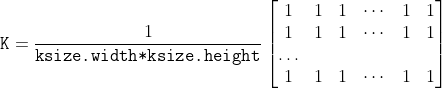
/// Blurs an image using the normalized box filter.
///
/// The function smooths an image using the kernel:
///
/// 
///
/// The call `blur(src, dst, ksize, anchor, borderType)` is equivalent to `boxFilter(src, dst, src.type(),
/// anchor, true, borderType)`.
///
/// ## Parameters
/// * src: input image; it can have any number of channels, which are processed independently, but
/// the depth should be CV_8U, CV_16U, CV_16S, CV_32F or CV_64F.
/// * dst: output image of the same size and type as src.
/// * ksize: blurring kernel size.
/// * anchor: anchor point; default value Point(-1,-1) means that the anchor is at the kernel
/// center.
/// * borderType: border mode used to extrapolate pixels outside of the image, see #BorderTypes
/// ## See also
/// boxFilter, bilateralFilter, GaussianBlur, medianBlur
///
/// ## C++ default parameters
/// * anchor: Point(-1,-1)
/// * border_type: BORDER_DEFAULT
pub fn blur(src: &dyn core::ToInputArray, dst: &mut dyn core::ToOutputArray, ksize: core::Size, anchor: core::Point, border_type: i32) -> Result<()> {
input_array_arg!(src);
output_array_arg!(dst);
unsafe { sys::cv_blur__InputArray__OutputArray_Size_Point_int(src.as_raw__InputArray(), dst.as_raw__OutputArray(), ksize, anchor, border_type) }.into_result()
}
/// Calculates the up-right bounding rectangle of a point set or non-zero pixels of gray-scale image.
///
/// The function calculates and returns the minimal up-right bounding rectangle for the specified point set or
/// non-zero pixels of gray-scale image.
///
/// ## Parameters
/// * array: Input gray-scale image or 2D point set, stored in std::vector or Mat.
pub fn bounding_rect(array: &dyn core::ToInputArray) -> Result<core::Rect> {
input_array_arg!(array);
unsafe { sys::cv_boundingRect__InputArray(array.as_raw__InputArray()) }.into_result()
}
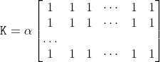
/// Blurs an image using the box filter.
///
/// The function smooths an image using the kernel:
///
/// 
///
/// where
///
/// 
///
/// Unnormalized box filter is useful for computing various integral characteristics over each pixel
/// neighborhood, such as covariance matrices of image derivatives (used in dense optical flow
/// algorithms, and so on). If you need to compute pixel sums over variable-size windows, use #integral.
///
/// ## Parameters
/// * src: input image.
/// * dst: output image of the same size and type as src.
/// * ddepth: the output image depth (-1 to use src.depth()).
/// * ksize: blurring kernel size.
/// * anchor: anchor point; default value Point(-1,-1) means that the anchor is at the kernel
/// center.
/// * normalize: flag, specifying whether the kernel is normalized by its area or not.
/// * borderType: border mode used to extrapolate pixels outside of the image, see #BorderTypes
/// ## See also
/// blur, bilateralFilter, GaussianBlur, medianBlur, integral
///
/// ## C++ default parameters
/// * anchor: Point(-1,-1)
/// * normalize: true
/// * border_type: BORDER_DEFAULT
pub fn box_filter(src: &dyn core::ToInputArray, dst: &mut dyn core::ToOutputArray, ddepth: i32, ksize: core::Size, anchor: core::Point, normalize: bool, border_type: i32) -> Result<()> {
input_array_arg!(src);
output_array_arg!(dst);
unsafe { sys::cv_boxFilter__InputArray__OutputArray_int_Size_Point_bool_int(src.as_raw__InputArray(), dst.as_raw__OutputArray(), ddepth, ksize, anchor, normalize, border_type) }.into_result()
}
/// Finds the four vertices of a rotated rect. Useful to draw the rotated rectangle.
///
/// The function finds the four vertices of a rotated rectangle. This function is useful to draw the
/// rectangle. In C++, instead of using this function, you can directly use RotatedRect::points method. Please
/// visit the @ref tutorial_bounding_rotated_ellipses "tutorial on Creating Bounding rotated boxes and ellipses for contours" for more information.
///
/// ## Parameters
/// * box: The input rotated rectangle. It may be the output of
/// * points: The output array of four vertices of rectangles.
pub fn box_points(_box: &core::RotatedRect, points: &mut dyn core::ToOutputArray) -> Result<()> {
output_array_arg!(points);
unsafe { sys::cv_boxPoints_RotatedRect__OutputArray(_box.as_raw_RotatedRect(), points.as_raw__OutputArray()) }.into_result()
}
/// Constructs the Gaussian pyramid for an image.
///
/// The function constructs a vector of images and builds the Gaussian pyramid by recursively applying
/// pyrDown to the previously built pyramid layers, starting from `dst[0]==src`.
///
/// ## Parameters
/// * src: Source image. Check pyrDown for the list of supported types.
/// * dst: Destination vector of maxlevel+1 images of the same type as src. dst[0] will be the
/// same as src. dst[1] is the next pyramid layer, a smoothed and down-sized src, and so on.
/// * maxlevel: 0-based index of the last (the smallest) pyramid layer. It must be non-negative.
/// * borderType: Pixel extrapolation method, see #BorderTypes (#BORDER_CONSTANT isn't supported)
///
/// ## C++ default parameters
/// * border_type: BORDER_DEFAULT
pub fn build_pyramid(src: &dyn core::ToInputArray, dst: &mut dyn core::ToOutputArray, maxlevel: i32, border_type: i32) -> Result<()> {
input_array_arg!(src);
output_array_arg!(dst);
unsafe { sys::cv_buildPyramid__InputArray__OutputArray_int_int(src.as_raw__InputArray(), dst.as_raw__OutputArray(), maxlevel, border_type) }.into_result()
}
/// Calculates the back projection of a histogram.
///
/// The function cv::calcBackProject calculates the back project of the histogram. That is, similarly to
/// #calcHist , at each location (x, y) the function collects the values from the selected channels
/// in the input images and finds the corresponding histogram bin. But instead of incrementing it, the
/// function reads the bin value, scales it by scale , and stores in backProject(x,y) . In terms of
/// statistics, the function computes probability of each element value in respect with the empirical
/// probability distribution represented by the histogram. See how, for example, you can find and track
/// a bright-colored object in a scene:
///
/// - Before tracking, show the object to the camera so that it covers almost the whole frame.
/// Calculate a hue histogram. The histogram may have strong maximums, corresponding to the dominant
/// colors in the object.
///
/// - When tracking, calculate a back projection of a hue plane of each input video frame using that
/// pre-computed histogram. Threshold the back projection to suppress weak colors. It may also make
/// sense to suppress pixels with non-sufficient color saturation and too dark or too bright pixels.
///
/// - Find connected components in the resulting picture and choose, for example, the largest
/// component.
///
/// This is an approximate algorithm of the CamShift color object tracker.
///
/// ## Parameters
/// * images: Source arrays. They all should have the same depth, CV_8U, CV_16U or CV_32F , and the same
/// size. Each of them can have an arbitrary number of channels.
/// * nimages: Number of source images.
/// * channels: The list of channels used to compute the back projection. The number of channels
/// must match the histogram dimensionality. The first array channels are numerated from 0 to
/// images[0].channels()-1 , the second array channels are counted from images[0].channels() to
/// images[0].channels() + images[1].channels()-1, and so on.
/// * hist: Input histogram that can be dense or sparse.
/// * backProject: Destination back projection array that is a single-channel array of the same
/// size and depth as images[0] .
/// * ranges: Array of arrays of the histogram bin boundaries in each dimension. See #calcHist .
/// * scale: Optional scale factor for the output back projection.
/// * uniform: Flag indicating whether the histogram is uniform or not (see above).
///
/// ## See also
/// calcHist, compareHist
///
/// ## Overloaded parameters
pub fn calc_back_project(images: &dyn core::ToInputArray, channels: &types::VectorOfint, hist: &dyn core::ToInputArray, dst: &mut dyn core::ToOutputArray, ranges: &types::VectorOffloat, scale: f64) -> Result<()> {
input_array_arg!(images);
input_array_arg!(hist);
output_array_arg!(dst);
unsafe { sys::cv_calcBackProject__InputArray_VectorOfint__InputArray__OutputArray_VectorOffloat_double(images.as_raw__InputArray(), channels.as_raw_VectorOfint(), hist.as_raw__InputArray(), dst.as_raw__OutputArray(), ranges.as_raw_VectorOffloat(), scale) }.into_result()
}
/// Calculates a histogram of a set of arrays.
///
/// The function cv::calcHist calculates the histogram of one or more arrays. The elements of a tuple used
/// to increment a histogram bin are taken from the corresponding input arrays at the same location. The
/// sample below shows how to compute a 2D Hue-Saturation histogram for a color image. :
/// @include snippets/imgproc_calcHist.cpp
///
/// ## Parameters
/// * images: Source arrays. They all should have the same depth, CV_8U, CV_16U or CV_32F , and the same
/// size. Each of them can have an arbitrary number of channels.
/// * nimages: Number of source images.
/// * channels: List of the dims channels used to compute the histogram. The first array channels
/// are numerated from 0 to images[0].channels()-1 , the second array channels are counted from
/// images[0].channels() to images[0].channels() + images[1].channels()-1, and so on.
/// * mask: Optional mask. If the matrix is not empty, it must be an 8-bit array of the same size
/// as images[i] . The non-zero mask elements mark the array elements counted in the histogram.
/// * hist: Output histogram, which is a dense or sparse dims -dimensional array.
/// * dims: Histogram dimensionality that must be positive and not greater than CV_MAX_DIMS
/// (equal to 32 in the current OpenCV version).
/// * histSize: Array of histogram sizes in each dimension.
/// * ranges: Array of the dims arrays of the histogram bin boundaries in each dimension. When the
/// histogram is uniform ( uniform =true), then for each dimension i it is enough to specify the lower
/// (inclusive) boundary  of the 0-th histogram bin and the upper (exclusive) boundary
///  for the last histogram bin histSize[i]-1 . That is, in case of a
/// uniform histogram each of ranges[i] is an array of 2 elements. When the histogram is not uniform (
/// uniform=false ), then each of ranges[i] contains histSize[i]+1 elements:
/// 
/// . The array elements, that are not between  and  , are not
/// counted in the histogram.
/// * uniform: Flag indicating whether the histogram is uniform or not (see above).
/// * accumulate: Accumulation flag. If it is set, the histogram is not cleared in the beginning
/// when it is allocated. This feature enables you to compute a single histogram from several sets of
/// arrays, or to update the histogram in time.
///
/// ## Overloaded parameters
///
/// ## C++ default parameters
/// * accumulate: false
pub fn calc_hist(images: &dyn core::ToInputArray, channels: &types::VectorOfint, mask: &dyn core::ToInputArray, hist: &mut dyn core::ToOutputArray, hist_size: &types::VectorOfint, ranges: &types::VectorOffloat, accumulate: bool) -> Result<()> {
input_array_arg!(images);
input_array_arg!(mask);
output_array_arg!(hist);
unsafe { sys::cv_calcHist__InputArray_VectorOfint__InputArray__OutputArray_VectorOfint_VectorOffloat_bool(images.as_raw__InputArray(), channels.as_raw_VectorOfint(), mask.as_raw__InputArray(), hist.as_raw__OutputArray(), hist_size.as_raw_VectorOfint(), ranges.as_raw_VectorOffloat(), accumulate) }.into_result()
}
/// Draws a circle.
///
/// The function cv::circle draws a simple or filled circle with a given center and radius.
/// ## Parameters
/// * img: Image where the circle is drawn.
/// * center: Center of the circle.
/// * radius: Radius of the circle.
/// * color: Circle color.
/// * thickness: Thickness of the circle outline, if positive. Negative values, like #FILLED,
/// mean that a filled circle is to be drawn.
/// * lineType: Type of the circle boundary. See #LineTypes
/// * shift: Number of fractional bits in the coordinates of the center and in the radius value.
///
/// ## C++ default parameters
/// * thickness: 1
/// * line_type: LINE_8
/// * shift: 0
pub fn circle(img: &mut dyn core::ToInputOutputArray, center: core::Point, radius: i32, color: core::Scalar, thickness: i32, line_type: i32, shift: i32) -> Result<()> {
input_output_array_arg!(img);
unsafe { sys::cv_circle__InputOutputArray_Point_int_Scalar_int_int_int(img.as_raw__InputOutputArray(), center, radius, color, thickness, line_type, shift) }.into_result()
}
/// Clips the line against the image rectangle.
///
/// The function cv::clipLine calculates a part of the line segment that is entirely within the specified
/// rectangle. it returns false if the line segment is completely outside the rectangle. Otherwise,
/// it returns true .
/// ## Parameters
/// * imgSize: Image size. The image rectangle is Rect(0, 0, imgSize.width, imgSize.height) .
/// * pt1: First line point.
/// * pt2: Second line point.
///
/// ## Overloaded parameters
///
/// * imgRect: Image rectangle.
/// * pt1: First line point.
/// * pt2: Second line point.
pub fn clip_line(img_rect: core::Rect, pt1: &mut core::Point, pt2: &mut core::Point) -> Result<bool> {
unsafe { sys::cv_clipLine_Rect_Point_Point(img_rect, pt1, pt2) }.into_result()
}
/// Clips the line against the image rectangle.
///
/// The function cv::clipLine calculates a part of the line segment that is entirely within the specified
/// rectangle. it returns false if the line segment is completely outside the rectangle. Otherwise,
/// it returns true .
/// ## Parameters
/// * imgSize: Image size. The image rectangle is Rect(0, 0, imgSize.width, imgSize.height) .
/// * pt1: First line point.
/// * pt2: Second line point.
///
/// ## Overloaded parameters
///
/// * imgSize: Image size. The image rectangle is Rect(0, 0, imgSize.width, imgSize.height) .
/// * pt1: First line point.
/// * pt2: Second line point.
pub fn clip_line_size_i64(img_size: core::Size2l, pt1: &mut core::Point2l, pt2: &mut core::Point2l) -> Result<bool> {
unsafe { sys::cv_clipLine_Size2l_Point2l_Point2l(img_size, pt1, pt2) }.into_result()
}
/// Clips the line against the image rectangle.
///
/// The function cv::clipLine calculates a part of the line segment that is entirely within the specified
/// rectangle. it returns false if the line segment is completely outside the rectangle. Otherwise,
/// it returns true .
/// ## Parameters
/// * imgSize: Image size. The image rectangle is Rect(0, 0, imgSize.width, imgSize.height) .
/// * pt1: First line point.
/// * pt2: Second line point.
pub fn clip_line_size(img_size: core::Size, pt1: &mut core::Point, pt2: &mut core::Point) -> Result<bool> {
unsafe { sys::cv_clipLine_Size_Point_Point(img_size, pt1, pt2) }.into_result()
}
/// Compares two histograms.
///
/// The function cv::compareHist compares two dense or two sparse histograms using the specified method.
///
/// The function returns  .
///
/// While the function works well with 1-, 2-, 3-dimensional dense histograms, it may not be suitable
/// for high-dimensional sparse histograms. In such histograms, because of aliasing and sampling
/// problems, the coordinates of non-zero histogram bins can slightly shift. To compare such histograms
/// or more general sparse configurations of weighted points, consider using the #EMD function.
///
/// ## Parameters
/// * H1: First compared histogram.
/// * H2: Second compared histogram of the same size as H1 .
/// * method: Comparison method, see #HistCompMethods
pub fn compare_hist(h1: &dyn core::ToInputArray, h2: &dyn core::ToInputArray, method: i32) -> Result<f64> {
input_array_arg!(h1);
input_array_arg!(h2);
unsafe { sys::cv_compareHist__InputArray__InputArray_int(h1.as_raw__InputArray(), h2.as_raw__InputArray(), method) }.into_result()
}
/// computes the connected components labeled image of boolean image and also produces a statistics output for each label
///
/// image with 4 or 8 way connectivity - returns N, the total number of labels [0, N-1] where 0
/// represents the background label. ltype specifies the output label image type, an important
/// consideration based on the total number of labels or alternatively the total number of pixels in
/// the source image. ccltype specifies the connected components labeling algorithm to use, currently
/// Grana's (BBDT) and Wu's (SAUF) algorithms are supported, see the #ConnectedComponentsAlgorithmsTypes
/// for details. Note that SAUF algorithm forces a row major ordering of labels while BBDT does not.
/// This function uses parallel version of both Grana and Wu's algorithms (statistics included) if at least one allowed
/// parallel framework is enabled and if the rows of the image are at least twice the number returned by #getNumberOfCPUs.
///
/// ## Parameters
/// * image: the 8-bit single-channel image to be labeled
/// * labels: destination labeled image
/// * stats: statistics output for each label, including the background label, see below for
/// available statistics. Statistics are accessed via stats(label, COLUMN) where COLUMN is one of
/// #ConnectedComponentsTypes. The data type is CV_32S.
/// * centroids: centroid output for each label, including the background label. Centroids are
/// accessed via centroids(label, 0) for x and centroids(label, 1) for y. The data type CV_64F.
/// * connectivity: 8 or 4 for 8-way or 4-way connectivity respectively
/// * ltype: output image label type. Currently CV_32S and CV_16U are supported.
/// * ccltype: connected components algorithm type (see #ConnectedComponentsAlgorithmsTypes).
///
/// ## Overloaded parameters
///
/// * image: the 8-bit single-channel image to be labeled
/// * labels: destination labeled image
/// * stats: statistics output for each label, including the background label, see below for
/// available statistics. Statistics are accessed via stats(label, COLUMN) where COLUMN is one of
/// #ConnectedComponentsTypes. The data type is CV_32S.
/// * centroids: centroid output for each label, including the background label. Centroids are
/// accessed via centroids(label, 0) for x and centroids(label, 1) for y. The data type CV_64F.
/// * connectivity: 8 or 4 for 8-way or 4-way connectivity respectively
/// * ltype: output image label type. Currently CV_32S and CV_16U are supported.
///
/// ## C++ default parameters
/// * connectivity: 8
/// * ltype: CV_32S
pub fn connected_components_with_stats(image: &dyn core::ToInputArray, labels: &mut dyn core::ToOutputArray, stats: &mut dyn core::ToOutputArray, centroids: &mut dyn core::ToOutputArray, connectivity: i32, ltype: i32) -> Result<i32> {
input_array_arg!(image);
output_array_arg!(labels);
output_array_arg!(stats);
output_array_arg!(centroids);
unsafe { sys::cv_connectedComponentsWithStats__InputArray__OutputArray__OutputArray__OutputArray_int_int(image.as_raw__InputArray(), labels.as_raw__OutputArray(), stats.as_raw__OutputArray(), centroids.as_raw__OutputArray(), connectivity, ltype) }.into_result()
}
/// computes the connected components labeled image of boolean image and also produces a statistics output for each label
///
/// image with 4 or 8 way connectivity - returns N, the total number of labels [0, N-1] where 0
/// represents the background label. ltype specifies the output label image type, an important
/// consideration based on the total number of labels or alternatively the total number of pixels in
/// the source image. ccltype specifies the connected components labeling algorithm to use, currently
/// Grana's (BBDT) and Wu's (SAUF) algorithms are supported, see the #ConnectedComponentsAlgorithmsTypes
/// for details. Note that SAUF algorithm forces a row major ordering of labels while BBDT does not.
/// This function uses parallel version of both Grana and Wu's algorithms (statistics included) if at least one allowed
/// parallel framework is enabled and if the rows of the image are at least twice the number returned by #getNumberOfCPUs.
///
/// ## Parameters
/// * image: the 8-bit single-channel image to be labeled
/// * labels: destination labeled image
/// * stats: statistics output for each label, including the background label, see below for
/// available statistics. Statistics are accessed via stats(label, COLUMN) where COLUMN is one of
/// #ConnectedComponentsTypes. The data type is CV_32S.
/// * centroids: centroid output for each label, including the background label. Centroids are
/// accessed via centroids(label, 0) for x and centroids(label, 1) for y. The data type CV_64F.
/// * connectivity: 8 or 4 for 8-way or 4-way connectivity respectively
/// * ltype: output image label type. Currently CV_32S and CV_16U are supported.
/// * ccltype: connected components algorithm type (see #ConnectedComponentsAlgorithmsTypes).
pub fn connected_components_with_stats_algo(image: &dyn core::ToInputArray, labels: &mut dyn core::ToOutputArray, stats: &mut dyn core::ToOutputArray, centroids: &mut dyn core::ToOutputArray, connectivity: i32, ltype: i32, ccltype: i32) -> Result<i32> {
input_array_arg!(image);
output_array_arg!(labels);
output_array_arg!(stats);
output_array_arg!(centroids);
unsafe { sys::cv_connectedComponentsWithStats__InputArray__OutputArray__OutputArray__OutputArray_int_int_int(image.as_raw__InputArray(), labels.as_raw__OutputArray(), stats.as_raw__OutputArray(), centroids.as_raw__OutputArray(), connectivity, ltype, ccltype) }.into_result()
}
/// computes the connected components labeled image of boolean image
///
/// image with 4 or 8 way connectivity - returns N, the total number of labels [0, N-1] where 0
/// represents the background label. ltype specifies the output label image type, an important
/// consideration based on the total number of labels or alternatively the total number of pixels in
/// the source image. ccltype specifies the connected components labeling algorithm to use, currently
/// Grana (BBDT) and Wu's (SAUF) algorithms are supported, see the #ConnectedComponentsAlgorithmsTypes
/// for details. Note that SAUF algorithm forces a row major ordering of labels while BBDT does not.
/// This function uses parallel version of both Grana and Wu's algorithms if at least one allowed
/// parallel framework is enabled and if the rows of the image are at least twice the number returned by #getNumberOfCPUs.
///
/// ## Parameters
/// * image: the 8-bit single-channel image to be labeled
/// * labels: destination labeled image
/// * connectivity: 8 or 4 for 8-way or 4-way connectivity respectively
/// * ltype: output image label type. Currently CV_32S and CV_16U are supported.
/// * ccltype: connected components algorithm type (see the #ConnectedComponentsAlgorithmsTypes).
///
/// ## Overloaded parameters
///
///
/// * image: the 8-bit single-channel image to be labeled
/// * labels: destination labeled image
/// * connectivity: 8 or 4 for 8-way or 4-way connectivity respectively
/// * ltype: output image label type. Currently CV_32S and CV_16U are supported.
///
/// ## C++ default parameters
/// * connectivity: 8
/// * ltype: CV_32S
pub fn connected_components(image: &dyn core::ToInputArray, labels: &mut dyn core::ToOutputArray, connectivity: i32, ltype: i32) -> Result<i32> {
input_array_arg!(image);
output_array_arg!(labels);
unsafe { sys::cv_connectedComponents__InputArray__OutputArray_int_int(image.as_raw__InputArray(), labels.as_raw__OutputArray(), connectivity, ltype) }.into_result()
}
/// computes the connected components labeled image of boolean image
///
/// image with 4 or 8 way connectivity - returns N, the total number of labels [0, N-1] where 0
/// represents the background label. ltype specifies the output label image type, an important
/// consideration based on the total number of labels or alternatively the total number of pixels in
/// the source image. ccltype specifies the connected components labeling algorithm to use, currently
/// Grana (BBDT) and Wu's (SAUF) algorithms are supported, see the #ConnectedComponentsAlgorithmsTypes
/// for details. Note that SAUF algorithm forces a row major ordering of labels while BBDT does not.
/// This function uses parallel version of both Grana and Wu's algorithms if at least one allowed
/// parallel framework is enabled and if the rows of the image are at least twice the number returned by #getNumberOfCPUs.
///
/// ## Parameters
/// * image: the 8-bit single-channel image to be labeled
/// * labels: destination labeled image
/// * connectivity: 8 or 4 for 8-way or 4-way connectivity respectively
/// * ltype: output image label type. Currently CV_32S and CV_16U are supported.
/// * ccltype: connected components algorithm type (see the #ConnectedComponentsAlgorithmsTypes).
pub fn connected_components_algo(image: &dyn core::ToInputArray, labels: &mut dyn core::ToOutputArray, connectivity: i32, ltype: i32, ccltype: i32) -> Result<i32> {
input_array_arg!(image);
output_array_arg!(labels);
unsafe { sys::cv_connectedComponents__InputArray__OutputArray_int_int_int(image.as_raw__InputArray(), labels.as_raw__OutputArray(), connectivity, ltype, ccltype) }.into_result()
}
/// Calculates a contour area.
///
/// The function computes a contour area. Similarly to moments , the area is computed using the Green
/// formula. Thus, the returned area and the number of non-zero pixels, if you draw the contour using
/// #drawContours or #fillPoly , can be different. Also, the function will most certainly give a wrong
/// results for contours with self-intersections.
///
/// Example:
/// ```ignore
/// vector<Point> contour;
/// contour.push_back(Point2f(0, 0));
/// contour.push_back(Point2f(10, 0));
/// contour.push_back(Point2f(10, 10));
/// contour.push_back(Point2f(5, 4));
///
/// double area0 = contourArea(contour);
/// vector<Point> approx;
/// approxPolyDP(contour, approx, 5, true);
/// double area1 = contourArea(approx);
///
/// cout << "area0 =" << area0 << endl <<
/// "area1 =" << area1 << endl <<
/// "approx poly vertices" << approx.size() << endl;
/// ```
///
/// ## Parameters
/// * contour: Input vector of 2D points (contour vertices), stored in std::vector or Mat.
/// * oriented: Oriented area flag. If it is true, the function returns a signed area value,
/// depending on the contour orientation (clockwise or counter-clockwise). Using this feature you can
/// determine orientation of a contour by taking the sign of an area. By default, the parameter is
/// false, which means that the absolute value is returned.
///
/// ## C++ default parameters
/// * oriented: false
pub fn contour_area(contour: &dyn core::ToInputArray, oriented: bool) -> Result<f64> {
input_array_arg!(contour);
unsafe { sys::cv_contourArea__InputArray_bool(contour.as_raw__InputArray(), oriented) }.into_result()
}
/// Converts image transformation maps from one representation to another.
///
/// The function converts a pair of maps for remap from one representation to another. The following
/// options ( (map1.type(), map2.type())  (dstmap1.type(), dstmap2.type()) ) are
/// supported:
///
/// - . This is the
/// most frequently used conversion operation, in which the original floating-point maps (see remap )
/// are converted to a more compact and much faster fixed-point representation. The first output array
/// contains the rounded coordinates and the second array (created only when nninterpolation=false )
/// contains indices in the interpolation tables.
///
/// - . The same as above but
/// the original maps are stored in one 2-channel matrix.
///
/// - Reverse conversion. Obviously, the reconstructed floating-point maps will not be exactly the same
/// as the originals.
///
/// ## Parameters
/// * map1: The first input map of type CV_16SC2, CV_32FC1, or CV_32FC2 .
/// * map2: The second input map of type CV_16UC1, CV_32FC1, or none (empty matrix),
/// respectively.
/// * dstmap1: The first output map that has the type dstmap1type and the same size as src .
/// * dstmap2: The second output map.
/// * dstmap1type: Type of the first output map that should be CV_16SC2, CV_32FC1, or
/// CV_32FC2 .
/// * nninterpolation: Flag indicating whether the fixed-point maps are used for the
/// nearest-neighbor or for a more complex interpolation.
///
/// ## See also
/// remap, undistort, initUndistortRectifyMap
///
/// ## C++ default parameters
/// * nninterpolation: false
pub fn convert_maps(map1: &dyn core::ToInputArray, map2: &dyn core::ToInputArray, dstmap1: &mut dyn core::ToOutputArray, dstmap2: &mut dyn core::ToOutputArray, dstmap1type: i32, nninterpolation: bool) -> Result<()> {
input_array_arg!(map1);
input_array_arg!(map2);
output_array_arg!(dstmap1);
output_array_arg!(dstmap2);
unsafe { sys::cv_convertMaps__InputArray__InputArray__OutputArray__OutputArray_int_bool(map1.as_raw__InputArray(), map2.as_raw__InputArray(), dstmap1.as_raw__OutputArray(), dstmap2.as_raw__OutputArray(), dstmap1type, nninterpolation) }.into_result()
}
/// Finds the convex hull of a point set.
///
/// The function cv::convexHull finds the convex hull of a 2D point set using the Sklansky's algorithm [Sklansky82](https://docs.opencv.org/3.4.7/d0/de3/citelist.html#CITEREF_Sklansky82)
/// that has *O(N logN)* complexity in the current implementation.
///
/// ## Parameters
/// * points: Input 2D point set, stored in std::vector or Mat.
/// * hull: Output convex hull. It is either an integer vector of indices or vector of points. In
/// the first case, the hull elements are 0-based indices of the convex hull points in the original
/// array (since the set of convex hull points is a subset of the original point set). In the second
/// case, hull elements are the convex hull points themselves.
/// * clockwise: Orientation flag. If it is true, the output convex hull is oriented clockwise.
/// Otherwise, it is oriented counter-clockwise. The assumed coordinate system has its X axis pointing
/// to the right, and its Y axis pointing upwards.
/// * returnPoints: Operation flag. In case of a matrix, when the flag is true, the function
/// returns convex hull points. Otherwise, it returns indices of the convex hull points. When the
/// output array is std::vector, the flag is ignored, and the output depends on the type of the
/// vector: std::vector\<int\> implies returnPoints=false, std::vector\<Point\> implies
/// returnPoints=true.
///
///
/// Note: `points` and `hull` should be different arrays, inplace processing isn't supported.
///
/// Check @ref tutorial_hull "the corresponding tutorial" for more details.
///
/// useful links:
///
/// https://www.learnopencv.com/convex-hull-using-opencv-in-python-and-c/
///
/// ## C++ default parameters
/// * clockwise: false
/// * return_points: true
pub fn convex_hull(points: &dyn core::ToInputArray, hull: &mut dyn core::ToOutputArray, clockwise: bool, return_points: bool) -> Result<()> {
input_array_arg!(points);
output_array_arg!(hull);
unsafe { sys::cv_convexHull__InputArray__OutputArray_bool_bool(points.as_raw__InputArray(), hull.as_raw__OutputArray(), clockwise, return_points) }.into_result()
}
/// Finds the convexity defects of a contour.
///
/// The figure below displays convexity defects of a hand contour:
///
/// 
///
/// ## Parameters
/// * contour: Input contour.
/// * convexhull: Convex hull obtained using convexHull that should contain indices of the contour
/// points that make the hull.
/// * convexityDefects: The output vector of convexity defects. In C++ and the new Python/Java
/// interface each convexity defect is represented as 4-element integer vector (a.k.a. #Vec4i):
/// (start_index, end_index, farthest_pt_index, fixpt_depth), where indices are 0-based indices
/// in the original contour of the convexity defect beginning, end and the farthest point, and
/// fixpt_depth is fixed-point approximation (with 8 fractional bits) of the distance between the
/// farthest contour point and the hull. That is, to get the floating-point value of the depth will be
/// fixpt_depth/256.0.
pub fn convexity_defects(contour: &dyn core::ToInputArray, convexhull: &dyn core::ToInputArray, convexity_defects: &mut dyn core::ToOutputArray) -> Result<()> {
input_array_arg!(contour);
input_array_arg!(convexhull);
output_array_arg!(convexity_defects);
unsafe { sys::cv_convexityDefects__InputArray__InputArray__OutputArray(contour.as_raw__InputArray(), convexhull.as_raw__InputArray(), convexity_defects.as_raw__OutputArray()) }.into_result()
}
/// Calculates eigenvalues and eigenvectors of image blocks for corner detection.
///
/// For every pixel  , the function cornerEigenValsAndVecs considers a blockSize  blockSize
/// neighborhood  . It calculates the covariation matrix of derivatives over the neighborhood as:
///
/// 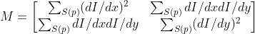
///
/// where the derivatives are computed using the Sobel operator.
///
/// After that, it finds eigenvectors and eigenvalues of  and stores them in the destination image as
///  where
///
/// *  are the non-sorted eigenvalues of 
/// *  are the eigenvectors corresponding to 
/// *  are the eigenvectors corresponding to 
///
/// The output of the function can be used for robust edge or corner detection.
///
/// ## Parameters
/// * src: Input single-channel 8-bit or floating-point image.
/// * dst: Image to store the results. It has the same size as src and the type CV_32FC(6) .
/// * blockSize: Neighborhood size (see details below).
/// * ksize: Aperture parameter for the Sobel operator.
/// * borderType: Pixel extrapolation method. See #BorderTypes.
///
/// ## See also
/// cornerMinEigenVal, cornerHarris, preCornerDetect
///
/// ## C++ default parameters
/// * border_type: BORDER_DEFAULT
pub fn corner_eigen_vals_and_vecs(src: &dyn core::ToInputArray, dst: &mut dyn core::ToOutputArray, block_size: i32, ksize: i32, border_type: i32) -> Result<()> {
input_array_arg!(src);
output_array_arg!(dst);
unsafe { sys::cv_cornerEigenValsAndVecs__InputArray__OutputArray_int_int_int(src.as_raw__InputArray(), dst.as_raw__OutputArray(), block_size, ksize, border_type) }.into_result()
}
/// Harris corner detector.
///
/// The function runs the Harris corner detector on the image. Similarly to cornerMinEigenVal and
/// cornerEigenValsAndVecs , for each pixel  it calculates a  gradient covariance
/// matrix  over a  neighborhood. Then, it
/// computes the following characteristic:
///
/// 
///
/// Corners in the image can be found as the local maxima of this response map.
///
/// ## Parameters
/// * src: Input single-channel 8-bit or floating-point image.
/// * dst: Image to store the Harris detector responses. It has the type CV_32FC1 and the same
/// size as src .
/// * blockSize: Neighborhood size (see the details on #cornerEigenValsAndVecs ).
/// * ksize: Aperture parameter for the Sobel operator.
/// * k: Harris detector free parameter. See the formula above.
/// * borderType: Pixel extrapolation method. See #BorderTypes.
///
/// ## C++ default parameters
/// * border_type: BORDER_DEFAULT
pub fn corner_harris(src: &dyn core::ToInputArray, dst: &mut dyn core::ToOutputArray, block_size: i32, ksize: i32, k: f64, border_type: i32) -> Result<()> {
input_array_arg!(src);
output_array_arg!(dst);
unsafe { sys::cv_cornerHarris__InputArray__OutputArray_int_int_double_int(src.as_raw__InputArray(), dst.as_raw__OutputArray(), block_size, ksize, k, border_type) }.into_result()
}
/// Calculates the minimal eigenvalue of gradient matrices for corner detection.
///
/// The function is similar to cornerEigenValsAndVecs but it calculates and stores only the minimal
/// eigenvalue of the covariance matrix of derivatives, that is,  in terms
/// of the formulae in the cornerEigenValsAndVecs description.
///
/// ## Parameters
/// * src: Input single-channel 8-bit or floating-point image.
/// * dst: Image to store the minimal eigenvalues. It has the type CV_32FC1 and the same size as
/// src .
/// * blockSize: Neighborhood size (see the details on #cornerEigenValsAndVecs ).
/// * ksize: Aperture parameter for the Sobel operator.
/// * borderType: Pixel extrapolation method. See #BorderTypes.
///
/// ## C++ default parameters
/// * ksize: 3
/// * border_type: BORDER_DEFAULT
pub fn corner_min_eigen_val(src: &dyn core::ToInputArray, dst: &mut dyn core::ToOutputArray, block_size: i32, ksize: i32, border_type: i32) -> Result<()> {
input_array_arg!(src);
output_array_arg!(dst);
unsafe { sys::cv_cornerMinEigenVal__InputArray__OutputArray_int_int_int(src.as_raw__InputArray(), dst.as_raw__OutputArray(), block_size, ksize, border_type) }.into_result()
}
/// Refines the corner locations.
///
/// The function iterates to find the sub-pixel accurate location of corners or radial saddle points, as
/// shown on the figure below.
///
/// 
///
/// Sub-pixel accurate corner locator is based on the observation that every vector from the center 
/// to a point  located within a neighborhood of  is orthogonal to the image gradient at 
/// subject to image and measurement noise. Consider the expression:
///
/// 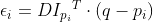
///
/// where  is an image gradient at one of the points  in a neighborhood of  . The
/// value of  is to be found so that  is minimized. A system of equations may be set up
/// with  set to zero:
///
/// 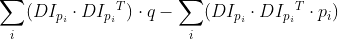
///
/// where the gradients are summed within a neighborhood ("search window") of  . Calling the first
/// gradient term  and the second gradient term  gives:
///
/// 
///
/// The algorithm sets the center of the neighborhood window at this new center  and then iterates
/// until the center stays within a set threshold.
///
/// ## Parameters
/// * image: Input single-channel, 8-bit or float image.
/// * corners: Initial coordinates of the input corners and refined coordinates provided for
/// output.
/// * winSize: Half of the side length of the search window. For example, if winSize=Size(5,5) ,
/// then a  search window is used.
/// * zeroZone: Half of the size of the dead region in the middle of the search zone over which
/// the summation in the formula below is not done. It is used sometimes to avoid possible
/// singularities of the autocorrelation matrix. The value of (-1,-1) indicates that there is no such
/// a size.
/// * criteria: Criteria for termination of the iterative process of corner refinement. That is,
/// the process of corner position refinement stops either after criteria.maxCount iterations or when
/// the corner position moves by less than criteria.epsilon on some iteration.
pub fn corner_sub_pix(image: &dyn core::ToInputArray, corners: &mut dyn core::ToInputOutputArray, win_size: core::Size, zero_zone: core::Size, criteria: &core::TermCriteria) -> Result<()> {
input_array_arg!(image);
input_output_array_arg!(corners);
unsafe { sys::cv_cornerSubPix__InputArray__InputOutputArray_Size_Size_TermCriteria(image.as_raw__InputArray(), corners.as_raw__InputOutputArray(), win_size, zero_zone, criteria.as_raw_TermCriteria()) }.into_result()
}
/// Creates a smart pointer to a cv::CLAHE class and initializes it.
///
/// ## Parameters
/// * clipLimit: Threshold for contrast limiting.
/// * tileGridSize: Size of grid for histogram equalization. Input image will be divided into
/// equally sized rectangular tiles. tileGridSize defines the number of tiles in row and column.
///
/// ## C++ default parameters
/// * clip_limit: 40.0
/// * tile_grid_size: Size(8, 8)
pub fn create_clahe(clip_limit: f64, tile_grid_size: core::Size) -> Result<types::PtrOfCLAHE> {
unsafe { sys::cv_createCLAHE_double_Size(clip_limit, tile_grid_size) }.into_result().map(|ptr| types::PtrOfCLAHE { ptr })
}
/// Creates a smart pointer to a cv::GeneralizedHoughBallard class and initializes it.
pub fn create_generalized_hough_ballard() -> Result<types::PtrOfGeneralizedHoughBallard> {
unsafe { sys::cv_createGeneralizedHoughBallard() }.into_result().map(|ptr| types::PtrOfGeneralizedHoughBallard { ptr })
}
/// Creates a smart pointer to a cv::GeneralizedHoughGuil class and initializes it.
pub fn create_generalized_hough_guil() -> Result<types::PtrOfGeneralizedHoughGuil> {
unsafe { sys::cv_createGeneralizedHoughGuil() }.into_result().map(|ptr| types::PtrOfGeneralizedHoughGuil { ptr })
}
/// This function computes a Hanning window coefficients in two dimensions.
///
/// See (http://en.wikipedia.org/wiki/Hann_function) and (http://en.wikipedia.org/wiki/Window_function)
/// for more information.
///
/// An example is shown below:
/// ```ignore
/// // create hanning window of size 100x100 and type CV_32F
/// Mat hann;
/// createHanningWindow(hann, Size(100, 100), CV_32F);
/// ```
///
/// ## Parameters
/// * dst: Destination array to place Hann coefficients in
/// * winSize: The window size specifications (both width and height must be > 1)
/// * type: Created array type
pub fn create_hanning_window(dst: &mut dyn core::ToOutputArray, win_size: core::Size, _type: i32) -> Result<()> {
output_array_arg!(dst);
unsafe { sys::cv_createHanningWindow__OutputArray_Size_int(dst.as_raw__OutputArray(), win_size, _type) }.into_result()
}
/// Creates a smart pointer to a LineSegmentDetector object and initializes it.
///
/// The LineSegmentDetector algorithm is defined using the standard values. Only advanced users may want
/// to edit those, as to tailor it for their own application.
///
/// ## Parameters
/// * _refine: The way found lines will be refined, see #LineSegmentDetectorModes
/// * _scale: The scale of the image that will be used to find the lines. Range (0..1].
/// * _sigma_scale: Sigma for Gaussian filter. It is computed as sigma = _sigma_scale/_scale.
/// * _quant: Bound to the quantization error on the gradient norm.
/// * _ang_th: Gradient angle tolerance in degrees.
/// * _log_eps: Detection threshold: -log10(NFA) \> log_eps. Used only when advance refinement
/// is chosen.
/// * _density_th: Minimal density of aligned region points in the enclosing rectangle.
/// * _n_bins: Number of bins in pseudo-ordering of gradient modulus.
///
///
/// Note: Implementation has been removed due original code license conflict
///
/// ## C++ default parameters
/// * _refine: LSD_REFINE_STD
/// * _scale: 0.8
/// * _sigma_scale: 0.6
/// * _quant: 2.0
/// * _ang_th: 22.5
/// * _log_eps: 0
/// * _density_th: 0.7
/// * _n_bins: 1024
pub fn create_line_segment_detector(_refine: i32, _scale: f64, _sigma_scale: f64, _quant: f64, _ang_th: f64, _log_eps: f64, _density_th: f64, _n_bins: i32) -> Result<types::PtrOfLineSegmentDetector> {
unsafe { sys::cv_createLineSegmentDetector_int_double_double_double_double_double_double_int(_refine, _scale, _sigma_scale, _quant, _ang_th, _log_eps, _density_th, _n_bins) }.into_result().map(|ptr| types::PtrOfLineSegmentDetector { ptr })
}
/// Converts an image from one color space to another where the source image is
/// stored in two planes.
///
/// This function only supports YUV420 to RGB conversion as of now.
///
/// ## Parameters
/// * src1: : 8-bit image (#CV_8U) of the Y plane.
/// * src2: : image containing interleaved U/V plane.
/// * dst: : output image.
/// * code: : Specifies the type of conversion. It can take any of the following values:
/// - #COLOR_YUV2BGR_NV12
/// - #COLOR_YUV2RGB_NV12
/// - #COLOR_YUV2BGRA_NV12
/// - #COLOR_YUV2RGBA_NV12
/// - #COLOR_YUV2BGR_NV21
/// - #COLOR_YUV2RGB_NV21
/// - #COLOR_YUV2BGRA_NV21
/// - #COLOR_YUV2RGBA_NV21
pub fn cvt_color_two_plane(src1: &dyn core::ToInputArray, src2: &dyn core::ToInputArray, dst: &mut dyn core::ToOutputArray, code: i32) -> Result<()> {
input_array_arg!(src1);
input_array_arg!(src2);
output_array_arg!(dst);
unsafe { sys::cv_cvtColorTwoPlane__InputArray__InputArray__OutputArray_int(src1.as_raw__InputArray(), src2.as_raw__InputArray(), dst.as_raw__OutputArray(), code) }.into_result()
}
/// Converts an image from one color space to another.
///
/// The function converts an input image from one color space to another. In case of a transformation
/// to-from RGB color space, the order of the channels should be specified explicitly (RGB or BGR). Note
/// that the default color format in OpenCV is often referred to as RGB but it is actually BGR (the
/// bytes are reversed). So the first byte in a standard (24-bit) color image will be an 8-bit Blue
/// component, the second byte will be Green, and the third byte will be Red. The fourth, fifth, and
/// sixth bytes would then be the second pixel (Blue, then Green, then Red), and so on.
///
/// The conventional ranges for R, G, and B channel values are:
/// * 0 to 255 for CV_8U images
/// * 0 to 65535 for CV_16U images
/// * 0 to 1 for CV_32F images
///
/// In case of linear transformations, the range does not matter. But in case of a non-linear
/// transformation, an input RGB image should be normalized to the proper value range to get the correct
/// results, for example, for RGB  L\*u\*v\* transformation. For example, if you have a
/// 32-bit floating-point image directly converted from an 8-bit image without any scaling, then it will
/// have the 0..255 value range instead of 0..1 assumed by the function. So, before calling #cvtColor ,
/// you need first to scale the image down:
/// ```ignore
/// img *= 1./255;
/// cvtColor(img, img, COLOR_BGR2Luv);
/// ```
///
/// If you use #cvtColor with 8-bit images, the conversion will have some information lost. For many
/// applications, this will not be noticeable but it is recommended to use 32-bit images in applications
/// that need the full range of colors or that convert an image before an operation and then convert
/// back.
///
/// If conversion adds the alpha channel, its value will set to the maximum of corresponding channel
/// range: 255 for CV_8U, 65535 for CV_16U, 1 for CV_32F.
///
/// ## Parameters
/// * src: input image: 8-bit unsigned, 16-bit unsigned ( CV_16UC... ), or single-precision
/// floating-point.
/// * dst: output image of the same size and depth as src.
/// * code: color space conversion code (see #ColorConversionCodes).
/// * dstCn: number of channels in the destination image; if the parameter is 0, the number of the
/// channels is derived automatically from src and code.
///
/// @see @ref imgproc_color_conversions
///
/// ## C++ default parameters
/// * dst_cn: 0
pub fn cvt_color(src: &dyn core::ToInputArray, dst: &mut dyn core::ToOutputArray, code: i32, dst_cn: i32) -> Result<()> {
input_array_arg!(src);
output_array_arg!(dst);
unsafe { sys::cv_cvtColor__InputArray__OutputArray_int_int(src.as_raw__InputArray(), dst.as_raw__OutputArray(), code, dst_cn) }.into_result()
}
/// main function for all demosaicing processes
///
/// ## Parameters
/// * src: input image: 8-bit unsigned or 16-bit unsigned.
/// * dst: output image of the same size and depth as src.
/// * code: Color space conversion code (see the description below).
/// * dstCn: number of channels in the destination image; if the parameter is 0, the number of the
/// channels is derived automatically from src and code.
///
/// The function can do the following transformations:
///
/// * Demosaicing using bilinear interpolation
///
/// #COLOR_BayerBG2BGR , #COLOR_BayerGB2BGR , #COLOR_BayerRG2BGR , #COLOR_BayerGR2BGR
///
/// #COLOR_BayerBG2GRAY , #COLOR_BayerGB2GRAY , #COLOR_BayerRG2GRAY , #COLOR_BayerGR2GRAY
///
/// * Demosaicing using Variable Number of Gradients.
///
/// #COLOR_BayerBG2BGR_VNG , #COLOR_BayerGB2BGR_VNG , #COLOR_BayerRG2BGR_VNG , #COLOR_BayerGR2BGR_VNG
///
/// * Edge-Aware Demosaicing.
///
/// #COLOR_BayerBG2BGR_EA , #COLOR_BayerGB2BGR_EA , #COLOR_BayerRG2BGR_EA , #COLOR_BayerGR2BGR_EA
///
/// * Demosaicing with alpha channel
///
/// #COLOR_BayerBG2BGRA , #COLOR_BayerGB2BGRA , #COLOR_BayerRG2BGRA , #COLOR_BayerGR2BGRA
///
/// ## See also
/// cvtColor
///
/// ## C++ default parameters
/// * dst_cn: 0
pub fn demosaicing(src: &dyn core::ToInputArray, dst: &mut dyn core::ToOutputArray, code: i32, dst_cn: i32) -> Result<()> {
input_array_arg!(src);
output_array_arg!(dst);
unsafe { sys::cv_demosaicing__InputArray__OutputArray_int_int(src.as_raw__InputArray(), dst.as_raw__OutputArray(), code, dst_cn) }.into_result()
}
/// Dilates an image by using a specific structuring element.
///
/// The function dilates the source image using the specified structuring element that determines the
/// shape of a pixel neighborhood over which the maximum is taken:
/// 
///
/// The function supports the in-place mode. Dilation can be applied several ( iterations ) times. In
/// case of multi-channel images, each channel is processed independently.
///
/// ## Parameters
/// * src: input image; the number of channels can be arbitrary, but the depth should be one of
/// CV_8U, CV_16U, CV_16S, CV_32F or CV_64F.
/// * dst: output image of the same size and type as src.
/// * kernel: structuring element used for dilation; if elemenat=Mat(), a 3 x 3 rectangular
/// structuring element is used. Kernel can be created using #getStructuringElement
/// * anchor: position of the anchor within the element; default value (-1, -1) means that the
/// anchor is at the element center.
/// * iterations: number of times dilation is applied.
/// * borderType: pixel extrapolation method, see #BorderTypes
/// * borderValue: border value in case of a constant border
/// ## See also
/// erode, morphologyEx, getStructuringElement
///
/// ## C++ default parameters
/// * anchor: Point(-1,-1)
/// * iterations: 1
/// * border_type: BORDER_CONSTANT
/// * border_value: morphologyDefaultBorderValue()
pub fn dilate(src: &dyn core::ToInputArray, dst: &mut dyn core::ToOutputArray, kernel: &dyn core::ToInputArray, anchor: core::Point, iterations: i32, border_type: i32, border_value: core::Scalar) -> Result<()> {
input_array_arg!(src);
output_array_arg!(dst);
input_array_arg!(kernel);
unsafe { sys::cv_dilate__InputArray__OutputArray__InputArray_Point_int_int_Scalar(src.as_raw__InputArray(), dst.as_raw__OutputArray(), kernel.as_raw__InputArray(), anchor, iterations, border_type, border_value) }.into_result()
}
/// Calculates the distance to the closest zero pixel for each pixel of the source image.
///
/// The function cv::distanceTransform calculates the approximate or precise distance from every binary
/// image pixel to the nearest zero pixel. For zero image pixels, the distance will obviously be zero.
///
/// When maskSize == #DIST_MASK_PRECISE and distanceType == #DIST_L2 , the function runs the
/// algorithm described in [Felzenszwalb04](https://docs.opencv.org/3.4.7/d0/de3/citelist.html#CITEREF_Felzenszwalb04) . This algorithm is parallelized with the TBB library.
///
/// In other cases, the algorithm [Borgefors86](https://docs.opencv.org/3.4.7/d0/de3/citelist.html#CITEREF_Borgefors86) is used. This means that for a pixel the function
/// finds the shortest path to the nearest zero pixel consisting of basic shifts: horizontal, vertical,
/// diagonal, or knight's move (the latest is available for a  mask). The overall
/// distance is calculated as a sum of these basic distances. Since the distance function should be
/// symmetric, all of the horizontal and vertical shifts must have the same cost (denoted as a ), all
/// the diagonal shifts must have the same cost (denoted as `b`), and all knight's moves must have the
/// same cost (denoted as `c`). For the #DIST_C and #DIST_L1 types, the distance is calculated
/// precisely, whereas for #DIST_L2 (Euclidean distance) the distance can be calculated only with a
/// relative error (a  mask gives more accurate results). For `a`,`b`, and `c`, OpenCV
/// uses the values suggested in the original paper:
/// - DIST_L1: `a = 1, b = 2`
/// - DIST_L2:
/// - `3 x 3`: `a=0.955, b=1.3693`
/// - `5 x 5`: `a=1, b=1.4, c=2.1969`
/// - DIST_C: `a = 1, b = 1`
///
/// Typically, for a fast, coarse distance estimation #DIST_L2, a  mask is used. For a
/// more accurate distance estimation #DIST_L2, a  mask or the precise algorithm is used.
/// Note that both the precise and the approximate algorithms are linear on the number of pixels.
///
/// This variant of the function does not only compute the minimum distance for each pixel 
/// but also identifies the nearest connected component consisting of zero pixels
/// (labelType==#DIST_LABEL_CCOMP) or the nearest zero pixel (labelType==#DIST_LABEL_PIXEL). Index of the
/// component/pixel is stored in `labels(x, y)`. When labelType==#DIST_LABEL_CCOMP, the function
/// automatically finds connected components of zero pixels in the input image and marks them with
/// distinct labels. When labelType==#DIST_LABEL_CCOMP, the function scans through the input image and
/// marks all the zero pixels with distinct labels.
///
/// In this mode, the complexity is still linear. That is, the function provides a very fast way to
/// compute the Voronoi diagram for a binary image. Currently, the second variant can use only the
/// approximate distance transform algorithm, i.e. maskSize=#DIST_MASK_PRECISE is not supported
/// yet.
///
/// ## Parameters
/// * src: 8-bit, single-channel (binary) source image.
/// * dst: Output image with calculated distances. It is a 8-bit or 32-bit floating-point,
/// single-channel image of the same size as src.
/// * labels: Output 2D array of labels (the discrete Voronoi diagram). It has the type
/// CV_32SC1 and the same size as src.
/// * distanceType: Type of distance, see #DistanceTypes
/// * maskSize: Size of the distance transform mask, see #DistanceTransformMasks.
/// #DIST_MASK_PRECISE is not supported by this variant. In case of the #DIST_L1 or #DIST_C distance type,
/// the parameter is forced to 3 because a  mask gives the same result as  or any larger aperture.
/// * labelType: Type of the label array to build, see #DistanceTransformLabelTypes.
///
/// ## C++ default parameters
/// * label_type: DIST_LABEL_CCOMP
pub fn distance_transform_labels(src: &dyn core::ToInputArray, dst: &mut dyn core::ToOutputArray, labels: &mut dyn core::ToOutputArray, distance_type: i32, mask_size: i32, label_type: i32) -> Result<()> {
input_array_arg!(src);
output_array_arg!(dst);
output_array_arg!(labels);
unsafe { sys::cv_distanceTransform__InputArray__OutputArray__OutputArray_int_int_int(src.as_raw__InputArray(), dst.as_raw__OutputArray(), labels.as_raw__OutputArray(), distance_type, mask_size, label_type) }.into_result()
}
/// Calculates the distance to the closest zero pixel for each pixel of the source image.
///
/// The function cv::distanceTransform calculates the approximate or precise distance from every binary
/// image pixel to the nearest zero pixel. For zero image pixels, the distance will obviously be zero.
///
/// When maskSize == #DIST_MASK_PRECISE and distanceType == #DIST_L2 , the function runs the
/// algorithm described in [Felzenszwalb04](https://docs.opencv.org/3.4.7/d0/de3/citelist.html#CITEREF_Felzenszwalb04) . This algorithm is parallelized with the TBB library.
///
/// In other cases, the algorithm [Borgefors86](https://docs.opencv.org/3.4.7/d0/de3/citelist.html#CITEREF_Borgefors86) is used. This means that for a pixel the function
/// finds the shortest path to the nearest zero pixel consisting of basic shifts: horizontal, vertical,
/// diagonal, or knight's move (the latest is available for a  mask). The overall
/// distance is calculated as a sum of these basic distances. Since the distance function should be
/// symmetric, all of the horizontal and vertical shifts must have the same cost (denoted as a ), all
/// the diagonal shifts must have the same cost (denoted as `b`), and all knight's moves must have the
/// same cost (denoted as `c`). For the #DIST_C and #DIST_L1 types, the distance is calculated
/// precisely, whereas for #DIST_L2 (Euclidean distance) the distance can be calculated only with a
/// relative error (a  mask gives more accurate results). For `a`,`b`, and `c`, OpenCV
/// uses the values suggested in the original paper:
/// - DIST_L1: `a = 1, b = 2`
/// - DIST_L2:
/// - `3 x 3`: `a=0.955, b=1.3693`
/// - `5 x 5`: `a=1, b=1.4, c=2.1969`
/// - DIST_C: `a = 1, b = 1`
///
/// Typically, for a fast, coarse distance estimation #DIST_L2, a  mask is used. For a
/// more accurate distance estimation #DIST_L2, a  mask or the precise algorithm is used.
/// Note that both the precise and the approximate algorithms are linear on the number of pixels.
///
/// This variant of the function does not only compute the minimum distance for each pixel 
/// but also identifies the nearest connected component consisting of zero pixels
/// (labelType==#DIST_LABEL_CCOMP) or the nearest zero pixel (labelType==#DIST_LABEL_PIXEL). Index of the
/// component/pixel is stored in `labels(x, y)`. When labelType==#DIST_LABEL_CCOMP, the function
/// automatically finds connected components of zero pixels in the input image and marks them with
/// distinct labels. When labelType==#DIST_LABEL_CCOMP, the function scans through the input image and
/// marks all the zero pixels with distinct labels.
///
/// In this mode, the complexity is still linear. That is, the function provides a very fast way to
/// compute the Voronoi diagram for a binary image. Currently, the second variant can use only the
/// approximate distance transform algorithm, i.e. maskSize=#DIST_MASK_PRECISE is not supported
/// yet.
///
/// ## Parameters
/// * src: 8-bit, single-channel (binary) source image.
/// * dst: Output image with calculated distances. It is a 8-bit or 32-bit floating-point,
/// single-channel image of the same size as src.
/// * labels: Output 2D array of labels (the discrete Voronoi diagram). It has the type
/// CV_32SC1 and the same size as src.
/// * distanceType: Type of distance, see #DistanceTypes
/// * maskSize: Size of the distance transform mask, see #DistanceTransformMasks.
/// #DIST_MASK_PRECISE is not supported by this variant. In case of the #DIST_L1 or #DIST_C distance type,
/// the parameter is forced to 3 because a  mask gives the same result as  or any larger aperture.
/// * labelType: Type of the label array to build, see #DistanceTransformLabelTypes.
///
/// ## Overloaded parameters
///
/// * src: 8-bit, single-channel (binary) source image.
/// * dst: Output image with calculated distances. It is a 8-bit or 32-bit floating-point,
/// single-channel image of the same size as src .
/// * distanceType: Type of distance, see #DistanceTypes
/// * maskSize: Size of the distance transform mask, see #DistanceTransformMasks. In case of the
/// #DIST_L1 or #DIST_C distance type, the parameter is forced to 3 because a  mask gives
/// the same result as  or any larger aperture.
/// * dstType: Type of output image. It can be CV_8U or CV_32F. Type CV_8U can be used only for
/// the first variant of the function and distanceType == #DIST_L1.
///
/// ## C++ default parameters
/// * dst_type: CV_32F
pub fn distance_transform(src: &dyn core::ToInputArray, dst: &mut dyn core::ToOutputArray, distance_type: i32, mask_size: i32, dst_type: i32) -> Result<()> {
input_array_arg!(src);
output_array_arg!(dst);
unsafe { sys::cv_distanceTransform__InputArray__OutputArray_int_int_int(src.as_raw__InputArray(), dst.as_raw__OutputArray(), distance_type, mask_size, dst_type) }.into_result()
}
/// Draws contours outlines or filled contours.
///
/// The function draws contour outlines in the image if  or fills the area
/// bounded by the contours if  . The example below shows how to retrieve
/// connected components from the binary image and label them: :
/// @include snippets/imgproc_drawContours.cpp
///
/// ## Parameters
/// * image: Destination image.
/// * contours: All the input contours. Each contour is stored as a point vector.
/// * contourIdx: Parameter indicating a contour to draw. If it is negative, all the contours are drawn.
/// * color: Color of the contours.
/// * thickness: Thickness of lines the contours are drawn with. If it is negative (for example,
/// thickness=#FILLED ), the contour interiors are drawn.
/// * lineType: Line connectivity. See #LineTypes
/// * hierarchy: Optional information about hierarchy. It is only needed if you want to draw only
/// some of the contours (see maxLevel ).
/// * maxLevel: Maximal level for drawn contours. If it is 0, only the specified contour is drawn.
/// If it is 1, the function draws the contour(s) and all the nested contours. If it is 2, the function
/// draws the contours, all the nested contours, all the nested-to-nested contours, and so on. This
/// parameter is only taken into account when there is hierarchy available.
/// * offset: Optional contour shift parameter. Shift all the drawn contours by the specified
///  .
///
/// Note: When thickness=#FILLED, the function is designed to handle connected components with holes correctly
/// even when no hierarchy date is provided. This is done by analyzing all the outlines together
/// using even-odd rule. This may give incorrect results if you have a joint collection of separately retrieved
/// contours. In order to solve this problem, you need to call #drawContours separately for each sub-group
/// of contours, or iterate over the collection using contourIdx parameter.
///
/// ## C++ default parameters
/// * thickness: 1
/// * line_type: LINE_8
/// * hierarchy: noArray()
/// * max_level: INT_MAX
/// * offset: Point()
pub fn draw_contours(image: &mut dyn core::ToInputOutputArray, contours: &dyn core::ToInputArray, contour_idx: i32, color: core::Scalar, thickness: i32, line_type: i32, hierarchy: &dyn core::ToInputArray, max_level: i32, offset: core::Point) -> Result<()> {
input_output_array_arg!(image);
input_array_arg!(contours);
input_array_arg!(hierarchy);
unsafe { sys::cv_drawContours__InputOutputArray__InputArray_int_Scalar_int_int__InputArray_int_Point(image.as_raw__InputOutputArray(), contours.as_raw__InputArray(), contour_idx, color, thickness, line_type, hierarchy.as_raw__InputArray(), max_level, offset) }.into_result()
}
/// Draws a marker on a predefined position in an image.
///
/// The function cv::drawMarker draws a marker on a given position in the image. For the moment several
/// marker types are supported, see #MarkerTypes for more information.
///
/// ## Parameters
/// * img: Image.
/// * position: The point where the crosshair is positioned.
/// * color: Line color.
/// * markerType: The specific type of marker you want to use, see #MarkerTypes
/// * thickness: Line thickness.
/// * line_type: Type of the line, See #LineTypes
/// * markerSize: The length of the marker axis [default = 20 pixels]
///
/// ## C++ default parameters
/// * marker_type: MARKER_CROSS
/// * marker_size: 20
/// * thickness: 1
/// * line_type: 8
pub fn draw_marker(img: &mut core::Mat, position: core::Point, color: core::Scalar, marker_type: i32, marker_size: i32, thickness: i32, line_type: i32) -> Result<()> {
unsafe { sys::cv_drawMarker_Mat_Point_Scalar_int_int_int_int(img.as_raw_Mat(), position, color, marker_type, marker_size, thickness, line_type) }.into_result()
}
/// Approximates an elliptic arc with a polyline.
///
/// The function ellipse2Poly computes the vertices of a polyline that approximates the specified
/// elliptic arc. It is used by #ellipse. If `arcStart` is greater than `arcEnd`, they are swapped.
///
/// ## Parameters
/// * center: Center of the arc.
/// * axes: Half of the size of the ellipse main axes. See #ellipse for details.
/// * angle: Rotation angle of the ellipse in degrees. See #ellipse for details.
/// * arcStart: Starting angle of the elliptic arc in degrees.
/// * arcEnd: Ending angle of the elliptic arc in degrees.
/// * delta: Angle between the subsequent polyline vertices. It defines the approximation
/// accuracy.
/// * pts: Output vector of polyline vertices.
///
/// ## Overloaded parameters
///
/// * center: Center of the arc.
/// * axes: Half of the size of the ellipse main axes. See #ellipse for details.
/// * angle: Rotation angle of the ellipse in degrees. See #ellipse for details.
/// * arcStart: Starting angle of the elliptic arc in degrees.
/// * arcEnd: Ending angle of the elliptic arc in degrees.
/// * delta: Angle between the subsequent polyline vertices. It defines the approximation accuracy.
/// * pts: Output vector of polyline vertices.
pub fn ellipse_2_poly_f64(center: core::Point2d, axes: core::Size2d, angle: i32, arc_start: i32, arc_end: i32, delta: i32, pts: &mut types::VectorOfPoint2d) -> Result<()> {
unsafe { sys::cv_ellipse2Poly_Point2d_Size2d_int_int_int_int_VectorOfPoint2d(center, axes, angle, arc_start, arc_end, delta, pts.as_raw_VectorOfPoint2d()) }.into_result()
}
/// Approximates an elliptic arc with a polyline.
///
/// The function ellipse2Poly computes the vertices of a polyline that approximates the specified
/// elliptic arc. It is used by #ellipse. If `arcStart` is greater than `arcEnd`, they are swapped.
///
/// ## Parameters
/// * center: Center of the arc.
/// * axes: Half of the size of the ellipse main axes. See #ellipse for details.
/// * angle: Rotation angle of the ellipse in degrees. See #ellipse for details.
/// * arcStart: Starting angle of the elliptic arc in degrees.
/// * arcEnd: Ending angle of the elliptic arc in degrees.
/// * delta: Angle between the subsequent polyline vertices. It defines the approximation
/// accuracy.
/// * pts: Output vector of polyline vertices.
pub fn ellipse_2_poly(center: core::Point, axes: core::Size, angle: i32, arc_start: i32, arc_end: i32, delta: i32, pts: &mut types::VectorOfPoint) -> Result<()> {
unsafe { sys::cv_ellipse2Poly_Point_Size_int_int_int_int_VectorOfPoint(center, axes, angle, arc_start, arc_end, delta, pts.as_raw_VectorOfPoint()) }.into_result()
}
/// Draws a simple or thick elliptic arc or fills an ellipse sector.
///
/// The function cv::ellipse with more parameters draws an ellipse outline, a filled ellipse, an elliptic
/// arc, or a filled ellipse sector. The drawing code uses general parametric form.
/// A piecewise-linear curve is used to approximate the elliptic arc
/// boundary. If you need more control of the ellipse rendering, you can retrieve the curve using
/// #ellipse2Poly and then render it with #polylines or fill it with #fillPoly. If you use the first
/// variant of the function and want to draw the whole ellipse, not an arc, pass `startAngle=0` and
/// `endAngle=360`. If `startAngle` is greater than `endAngle`, they are swapped. The figure below explains
/// the meaning of the parameters to draw the blue arc.
///
/// 
///
/// ## Parameters
/// * img: Image.
/// * center: Center of the ellipse.
/// * axes: Half of the size of the ellipse main axes.
/// * angle: Ellipse rotation angle in degrees.
/// * startAngle: Starting angle of the elliptic arc in degrees.
/// * endAngle: Ending angle of the elliptic arc in degrees.
/// * color: Ellipse color.
/// * thickness: Thickness of the ellipse arc outline, if positive. Otherwise, this indicates that
/// a filled ellipse sector is to be drawn.
/// * lineType: Type of the ellipse boundary. See #LineTypes
/// * shift: Number of fractional bits in the coordinates of the center and values of axes.
///
/// ## C++ default parameters
/// * thickness: 1
/// * line_type: LINE_8
/// * shift: 0
pub fn ellipse(img: &mut dyn core::ToInputOutputArray, center: core::Point, axes: core::Size, angle: f64, start_angle: f64, end_angle: f64, color: core::Scalar, thickness: i32, line_type: i32, shift: i32) -> Result<()> {
input_output_array_arg!(img);
unsafe { sys::cv_ellipse__InputOutputArray_Point_Size_double_double_double_Scalar_int_int_int(img.as_raw__InputOutputArray(), center, axes, angle, start_angle, end_angle, color, thickness, line_type, shift) }.into_result()
}
/// Draws a simple or thick elliptic arc or fills an ellipse sector.
///
/// The function cv::ellipse with more parameters draws an ellipse outline, a filled ellipse, an elliptic
/// arc, or a filled ellipse sector. The drawing code uses general parametric form.
/// A piecewise-linear curve is used to approximate the elliptic arc
/// boundary. If you need more control of the ellipse rendering, you can retrieve the curve using
/// #ellipse2Poly and then render it with #polylines or fill it with #fillPoly. If you use the first
/// variant of the function and want to draw the whole ellipse, not an arc, pass `startAngle=0` and
/// `endAngle=360`. If `startAngle` is greater than `endAngle`, they are swapped. The figure below explains
/// the meaning of the parameters to draw the blue arc.
///
/// 
///
/// ## Parameters
/// * img: Image.
/// * center: Center of the ellipse.
/// * axes: Half of the size of the ellipse main axes.
/// * angle: Ellipse rotation angle in degrees.
/// * startAngle: Starting angle of the elliptic arc in degrees.
/// * endAngle: Ending angle of the elliptic arc in degrees.
/// * color: Ellipse color.
/// * thickness: Thickness of the ellipse arc outline, if positive. Otherwise, this indicates that
/// a filled ellipse sector is to be drawn.
/// * lineType: Type of the ellipse boundary. See #LineTypes
/// * shift: Number of fractional bits in the coordinates of the center and values of axes.
///
/// ## Overloaded parameters
///
/// * img: Image.
/// * box: Alternative ellipse representation via RotatedRect. This means that the function draws
/// an ellipse inscribed in the rotated rectangle.
/// * color: Ellipse color.
/// * thickness: Thickness of the ellipse arc outline, if positive. Otherwise, this indicates that
/// a filled ellipse sector is to be drawn.
/// * lineType: Type of the ellipse boundary. See #LineTypes
///
/// ## C++ default parameters
/// * thickness: 1
/// * line_type: LINE_8
pub fn ellipse_new_rotated_rect(img: &mut dyn core::ToInputOutputArray, _box: &core::RotatedRect, color: core::Scalar, thickness: i32, line_type: i32) -> Result<()> {
input_output_array_arg!(img);
unsafe { sys::cv_ellipse__InputOutputArray_RotatedRect_Scalar_int_int(img.as_raw__InputOutputArray(), _box.as_raw_RotatedRect(), color, thickness, line_type) }.into_result()
}
/// Equalizes the histogram of a grayscale image.
///
/// The function equalizes the histogram of the input image using the following algorithm:
///
/// - Calculate the histogram  for src .
/// - Normalize the histogram so that the sum of histogram bins is 255.
/// - Compute the integral of the histogram:
/// 
/// - Transform the image using  as a look-up table: 
///
/// The algorithm normalizes the brightness and increases the contrast of the image.
///
/// ## Parameters
/// * src: Source 8-bit single channel image.
/// * dst: Destination image of the same size and type as src .
pub fn equalize_hist(src: &dyn core::ToInputArray, dst: &mut dyn core::ToOutputArray) -> Result<()> {
input_array_arg!(src);
output_array_arg!(dst);
unsafe { sys::cv_equalizeHist__InputArray__OutputArray(src.as_raw__InputArray(), dst.as_raw__OutputArray()) }.into_result()
}
/// Erodes an image by using a specific structuring element.
///
/// The function erodes the source image using the specified structuring element that determines the
/// shape of a pixel neighborhood over which the minimum is taken:
///
/// 
///
/// The function supports the in-place mode. Erosion can be applied several ( iterations ) times. In
/// case of multi-channel images, each channel is processed independently.
///
/// ## Parameters
/// * src: input image; the number of channels can be arbitrary, but the depth should be one of
/// CV_8U, CV_16U, CV_16S, CV_32F or CV_64F.
/// * dst: output image of the same size and type as src.
/// * kernel: structuring element used for erosion; if `element=Mat()`, a `3 x 3` rectangular
/// structuring element is used. Kernel can be created using #getStructuringElement.
/// * anchor: position of the anchor within the element; default value (-1, -1) means that the
/// anchor is at the element center.
/// * iterations: number of times erosion is applied.
/// * borderType: pixel extrapolation method, see #BorderTypes
/// * borderValue: border value in case of a constant border
/// ## See also
/// dilate, morphologyEx, getStructuringElement
///
/// ## C++ default parameters
/// * anchor: Point(-1,-1)
/// * iterations: 1
/// * border_type: BORDER_CONSTANT
/// * border_value: morphologyDefaultBorderValue()
pub fn erode(src: &dyn core::ToInputArray, dst: &mut dyn core::ToOutputArray, kernel: &dyn core::ToInputArray, anchor: core::Point, iterations: i32, border_type: i32, border_value: core::Scalar) -> Result<()> {
input_array_arg!(src);
output_array_arg!(dst);
input_array_arg!(kernel);
unsafe { sys::cv_erode__InputArray__OutputArray__InputArray_Point_int_int_Scalar(src.as_raw__InputArray(), dst.as_raw__OutputArray(), kernel.as_raw__InputArray(), anchor, iterations, border_type, border_value) }.into_result()
}
/// Fills a convex polygon.
///
/// The function cv::fillConvexPoly draws a filled convex polygon. This function is much faster than the
/// function #fillPoly . It can fill not only convex polygons but any monotonic polygon without
/// self-intersections, that is, a polygon whose contour intersects every horizontal line (scan line)
/// twice at the most (though, its top-most and/or the bottom edge could be horizontal).
///
/// ## Parameters
/// * img: Image.
/// * points: Polygon vertices.
/// * color: Polygon color.
/// * lineType: Type of the polygon boundaries. See #LineTypes
/// * shift: Number of fractional bits in the vertex coordinates.
///
/// ## C++ default parameters
/// * line_type: LINE_8
/// * shift: 0
pub fn fill_convex_poly(img: &mut dyn core::ToInputOutputArray, points: &dyn core::ToInputArray, color: core::Scalar, line_type: i32, shift: i32) -> Result<()> {
input_output_array_arg!(img);
input_array_arg!(points);
unsafe { sys::cv_fillConvexPoly__InputOutputArray__InputArray_Scalar_int_int(img.as_raw__InputOutputArray(), points.as_raw__InputArray(), color, line_type, shift) }.into_result()
}
/// Fills the area bounded by one or more polygons.
///
/// The function cv::fillPoly fills an area bounded by several polygonal contours. The function can fill
/// complex areas, for example, areas with holes, contours with self-intersections (some of their
/// parts), and so forth.
///
/// ## Parameters
/// * img: Image.
/// * pts: Array of polygons where each polygon is represented as an array of points.
/// * color: Polygon color.
/// * lineType: Type of the polygon boundaries. See #LineTypes
/// * shift: Number of fractional bits in the vertex coordinates.
/// * offset: Optional offset of all points of the contours.
///
/// ## C++ default parameters
/// * line_type: LINE_8
/// * shift: 0
/// * offset: Point()
pub fn fill_poly(img: &mut dyn core::ToInputOutputArray, pts: &dyn core::ToInputArray, color: core::Scalar, line_type: i32, shift: i32, offset: core::Point) -> Result<()> {
input_output_array_arg!(img);
input_array_arg!(pts);
unsafe { sys::cv_fillPoly__InputOutputArray__InputArray_Scalar_int_int_Point(img.as_raw__InputOutputArray(), pts.as_raw__InputArray(), color, line_type, shift, offset) }.into_result()
}
/// Convolves an image with the kernel.
///
/// The function applies an arbitrary linear filter to an image. In-place operation is supported. When
/// the aperture is partially outside the image, the function interpolates outlier pixel values
/// according to the specified border mode.
///
/// The function does actually compute correlation, not the convolution:
///
/// 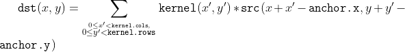
///
/// That is, the kernel is not mirrored around the anchor point. If you need a real convolution, flip
/// the kernel using #flip and set the new anchor to `(kernel.cols - anchor.x - 1, kernel.rows -
/// anchor.y - 1)`.
///
/// The function uses the DFT-based algorithm in case of sufficiently large kernels (~`11 x 11` or
/// larger) and the direct algorithm for small kernels.
///
/// ## Parameters
/// * src: input image.
/// * dst: output image of the same size and the same number of channels as src.
/// * ddepth: desired depth of the destination image, see @ref filter_depths "combinations"
/// * kernel: convolution kernel (or rather a correlation kernel), a single-channel floating point
/// matrix; if you want to apply different kernels to different channels, split the image into
/// separate color planes using split and process them individually.
/// * anchor: anchor of the kernel that indicates the relative position of a filtered point within
/// the kernel; the anchor should lie within the kernel; default value (-1,-1) means that the anchor
/// is at the kernel center.
/// * delta: optional value added to the filtered pixels before storing them in dst.
/// * borderType: pixel extrapolation method, see #BorderTypes
/// ## See also
/// sepFilter2D, dft, matchTemplate
///
/// ## C++ default parameters
/// * anchor: Point(-1,-1)
/// * delta: 0
/// * border_type: BORDER_DEFAULT
pub fn filter_2d(src: &dyn core::ToInputArray, dst: &mut dyn core::ToOutputArray, ddepth: i32, kernel: &dyn core::ToInputArray, anchor: core::Point, delta: f64, border_type: i32) -> Result<()> {
input_array_arg!(src);
output_array_arg!(dst);
input_array_arg!(kernel);
unsafe { sys::cv_filter2D__InputArray__OutputArray_int__InputArray_Point_double_int(src.as_raw__InputArray(), dst.as_raw__OutputArray(), ddepth, kernel.as_raw__InputArray(), anchor, delta, border_type) }.into_result()
}
/// Finds contours in a binary image.
///
/// The function retrieves contours from the binary image using the algorithm [Suzuki85](https://docs.opencv.org/3.4.7/d0/de3/citelist.html#CITEREF_Suzuki85) . The contours
/// are a useful tool for shape analysis and object detection and recognition. See squares.cpp in the
/// OpenCV sample directory.
///
/// Note: Since opencv 3.2 source image is not modified by this function.
///
/// ## Parameters
/// * image: Source, an 8-bit single-channel image. Non-zero pixels are treated as 1's. Zero
/// pixels remain 0's, so the image is treated as binary . You can use #compare, #inRange, #threshold ,
/// #adaptiveThreshold, #Canny, and others to create a binary image out of a grayscale or color one.
/// If mode equals to #RETR_CCOMP or #RETR_FLOODFILL, the input can also be a 32-bit integer image of labels (CV_32SC1).
/// * contours: Detected contours. Each contour is stored as a vector of points (e.g.
/// std::vector<std::vector<cv::Point> >).
/// * hierarchy: Optional output vector (e.g. std::vector<cv::Vec4i>), containing information about the image topology. It has
/// as many elements as the number of contours. For each i-th contour contours[i], the elements
/// hierarchy[i][0] , hierarchy[i][1] , hierarchy[i][2] , and hierarchy[i][3] are set to 0-based indices
/// in contours of the next and previous contours at the same hierarchical level, the first child
/// contour and the parent contour, respectively. If for the contour i there are no next, previous,
/// parent, or nested contours, the corresponding elements of hierarchy[i] will be negative.
/// * mode: Contour retrieval mode, see #RetrievalModes
/// * method: Contour approximation method, see #ContourApproximationModes
/// * offset: Optional offset by which every contour point is shifted. This is useful if the
/// contours are extracted from the image ROI and then they should be analyzed in the whole image
/// context.
///
/// ## C++ default parameters
/// * offset: Point()
pub fn find_contours_with_hierarchy(image: &mut dyn core::ToInputOutputArray, contours: &mut dyn core::ToOutputArray, hierarchy: &mut dyn core::ToOutputArray, mode: i32, method: i32, offset: core::Point) -> Result<()> {
input_output_array_arg!(image);
output_array_arg!(contours);
output_array_arg!(hierarchy);
unsafe { sys::cv_findContours__InputOutputArray__OutputArray__OutputArray_int_int_Point(image.as_raw__InputOutputArray(), contours.as_raw__OutputArray(), hierarchy.as_raw__OutputArray(), mode, method, offset) }.into_result()
}
/// Finds contours in a binary image.
///
/// The function retrieves contours from the binary image using the algorithm [Suzuki85](https://docs.opencv.org/3.4.7/d0/de3/citelist.html#CITEREF_Suzuki85) . The contours
/// are a useful tool for shape analysis and object detection and recognition. See squares.cpp in the
/// OpenCV sample directory.
///
/// Note: Since opencv 3.2 source image is not modified by this function.
///
/// ## Parameters
/// * image: Source, an 8-bit single-channel image. Non-zero pixels are treated as 1's. Zero
/// pixels remain 0's, so the image is treated as binary . You can use #compare, #inRange, #threshold ,
/// #adaptiveThreshold, #Canny, and others to create a binary image out of a grayscale or color one.
/// If mode equals to #RETR_CCOMP or #RETR_FLOODFILL, the input can also be a 32-bit integer image of labels (CV_32SC1).
/// * contours: Detected contours. Each contour is stored as a vector of points (e.g.
/// std::vector<std::vector<cv::Point> >).
/// * hierarchy: Optional output vector (e.g. std::vector<cv::Vec4i>), containing information about the image topology. It has
/// as many elements as the number of contours. For each i-th contour contours[i], the elements
/// hierarchy[i][0] , hierarchy[i][1] , hierarchy[i][2] , and hierarchy[i][3] are set to 0-based indices
/// in contours of the next and previous contours at the same hierarchical level, the first child
/// contour and the parent contour, respectively. If for the contour i there are no next, previous,
/// parent, or nested contours, the corresponding elements of hierarchy[i] will be negative.
/// * mode: Contour retrieval mode, see #RetrievalModes
/// * method: Contour approximation method, see #ContourApproximationModes
/// * offset: Optional offset by which every contour point is shifted. This is useful if the
/// contours are extracted from the image ROI and then they should be analyzed in the whole image
/// context.
///
/// ## Overloaded parameters
///
/// ## C++ default parameters
/// * offset: Point()
pub fn find_contours(image: &mut dyn core::ToInputOutputArray, contours: &mut dyn core::ToOutputArray, mode: i32, method: i32, offset: core::Point) -> Result<()> {
input_output_array_arg!(image);
output_array_arg!(contours);
unsafe { sys::cv_findContours__InputOutputArray__OutputArray_int_int_Point(image.as_raw__InputOutputArray(), contours.as_raw__OutputArray(), mode, method, offset) }.into_result()
}
/// Fits an ellipse around a set of 2D points.
///
/// The function calculates the ellipse that fits a set of 2D points.
/// It returns the rotated rectangle in which the ellipse is inscribed.
/// The Approximate Mean Square (AMS) proposed by [Taubin1991](https://docs.opencv.org/3.4.7/d0/de3/citelist.html#CITEREF_Taubin1991) is used.
///
/// For an ellipse, this basis set is 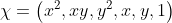,
/// which is a set of six free coefficients .
/// However, to specify an ellipse, all that is needed is five numbers; the major and minor axes lengths ,
/// the position , and the orientation . This is because the basis set includes lines,
/// quadratics, parabolic and hyperbolic functions as well as elliptical functions as possible fits.
/// If the fit is found to be a parabolic or hyperbolic function then the standard #fitEllipse method is used.
/// The AMS method restricts the fit to parabolic, hyperbolic and elliptical curves
/// by imposing the condition that 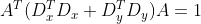 where
/// the matrices  and  are the partial derivatives of the design matrix  with
/// respect to x and y. The matrices are formed row by row applying the following to
/// each of the points in the set:
/// \f{align*}{
/// D(i,:)&=\left\{x_i^2, x_i y_i, y_i^2, x_i, y_i, 1\right\} &
/// D_x(i,:)&=\left\{2 x_i,y_i,0,1,0,0\right\} &
/// D_y(i,:)&=\left\{0,x_i,2 y_i,0,1,0\right\}
/// \f}
/// The AMS method minimizes the cost function
/// \f{equation*}{
/// \epsilon ^2=\frac{ A^T D^T D A }{ A^T (D_x^T D_x + D_y^T D_y) A^T }
/// \f}
///
/// The minimum cost is found by solving the generalized eigenvalue problem.
///
/// \f{equation*}{
/// D^T D A = \lambda \left( D_x^T D_x + D_y^T D_y\right) A
/// \f}
///
/// ## Parameters
/// * points: Input 2D point set, stored in std::vector\<\> or Mat
pub fn fit_ellipse_ams(points: &dyn core::ToInputArray) -> Result<core::RotatedRect> {
input_array_arg!(points);
unsafe { sys::cv_fitEllipseAMS__InputArray(points.as_raw__InputArray()) }.into_result().map(|ptr| core::RotatedRect { ptr })
}
/// Fits an ellipse around a set of 2D points.
///
/// The function calculates the ellipse that fits a set of 2D points.
/// It returns the rotated rectangle in which the ellipse is inscribed.
/// The Direct least square (Direct) method by [Fitzgibbon1999](https://docs.opencv.org/3.4.7/d0/de3/citelist.html#CITEREF_Fitzgibbon1999) is used.
///
/// For an ellipse, this basis set is ,
/// which is a set of six free coefficients .
/// However, to specify an ellipse, all that is needed is five numbers; the major and minor axes lengths ,
/// the position , and the orientation . This is because the basis set includes lines,
/// quadratics, parabolic and hyperbolic functions as well as elliptical functions as possible fits.
/// The Direct method confines the fit to ellipses by ensuring that .
/// The condition imposed is that  which satisfies the inequality
/// and as the coefficients can be arbitrarily scaled is not overly restrictive.
///
/// \f{equation*}{
/// \epsilon ^2= A^T D^T D A \quad \text{with} \quad A^T C A =1 \quad \text{and} \quad C=\left(\begin{matrix}
/// 0 & 0 & 2 & 0 & 0 & 0 \\
/// 0 & -1 & 0 & 0 & 0 & 0 \\
/// 2 & 0 & 0 & 0 & 0 & 0 \\
/// 0 & 0 & 0 & 0 & 0 & 0 \\
/// 0 & 0 & 0 & 0 & 0 & 0 \\
/// 0 & 0 & 0 & 0 & 0 & 0
/// \end{matrix} \right)
/// \f}
///
/// The minimum cost is found by solving the generalized eigenvalue problem.
///
/// \f{equation*}{
/// D^T D A = \lambda \left( C\right) A
/// \f}
///
/// The system produces only one positive eigenvalue  which is chosen as the solution
/// with its eigenvector . These are used to find the coefficients
///
/// \f{equation*}{
/// A = \sqrt{\frac{1}{\mathbf{u}^T C \mathbf{u}}} \mathbf{u}
/// \f}
/// The scaling factor guarantees that .
///
/// ## Parameters
/// * points: Input 2D point set, stored in std::vector\<\> or Mat
pub fn fit_ellipse_direct(points: &dyn core::ToInputArray) -> Result<core::RotatedRect> {
input_array_arg!(points);
unsafe { sys::cv_fitEllipseDirect__InputArray(points.as_raw__InputArray()) }.into_result().map(|ptr| core::RotatedRect { ptr })
}
/// Fits an ellipse around a set of 2D points.
///
/// The function calculates the ellipse that fits (in a least-squares sense) a set of 2D points best of
/// all. It returns the rotated rectangle in which the ellipse is inscribed. The first algorithm described by [Fitzgibbon95](https://docs.opencv.org/3.4.7/d0/de3/citelist.html#CITEREF_Fitzgibbon95)
/// is used. Developer should keep in mind that it is possible that the returned
/// ellipse/rotatedRect data contains negative indices, due to the data points being close to the
/// border of the containing Mat element.
///
/// ## Parameters
/// * points: Input 2D point set, stored in std::vector\<\> or Mat
pub fn fit_ellipse(points: &dyn core::ToInputArray) -> Result<core::RotatedRect> {
input_array_arg!(points);
unsafe { sys::cv_fitEllipse__InputArray(points.as_raw__InputArray()) }.into_result().map(|ptr| core::RotatedRect { ptr })
}
/// Fits a line to a 2D or 3D point set.
///
/// The function fitLine fits a line to a 2D or 3D point set by minimizing  where
///  is a distance between the  point, the line and  is a distance function, one
/// of the following:
/// * DIST_L2
/// 
/// - DIST_L1
/// 
/// - DIST_L12
/// 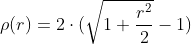
/// - DIST_FAIR
/// 
/// - DIST_WELSCH
/// 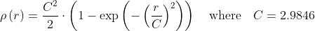
/// - DIST_HUBER
/// 
///
/// The algorithm is based on the M-estimator ( <http://en.wikipedia.org/wiki/M-estimator> ) technique
/// that iteratively fits the line using the weighted least-squares algorithm. After each iteration the
/// weights  are adjusted to be inversely proportional to  .
///
/// ## Parameters
/// * points: Input vector of 2D or 3D points, stored in std::vector\<\> or Mat.
/// * line: Output line parameters. In case of 2D fitting, it should be a vector of 4 elements
/// (like Vec4f) - (vx, vy, x0, y0), where (vx, vy) is a normalized vector collinear to the line and
/// (x0, y0) is a point on the line. In case of 3D fitting, it should be a vector of 6 elements (like
/// Vec6f) - (vx, vy, vz, x0, y0, z0), where (vx, vy, vz) is a normalized vector collinear to the line
/// and (x0, y0, z0) is a point on the line.
/// * distType: Distance used by the M-estimator, see #DistanceTypes
/// * param: Numerical parameter ( C ) for some types of distances. If it is 0, an optimal value
/// is chosen.
/// * reps: Sufficient accuracy for the radius (distance between the coordinate origin and the line).
/// * aeps: Sufficient accuracy for the angle. 0.01 would be a good default value for reps and aeps.
pub fn fit_line(points: &dyn core::ToInputArray, line: &mut dyn core::ToOutputArray, dist_type: i32, param: f64, reps: f64, aeps: f64) -> Result<()> {
input_array_arg!(points);
output_array_arg!(line);
unsafe { sys::cv_fitLine__InputArray__OutputArray_int_double_double_double(points.as_raw__InputArray(), line.as_raw__OutputArray(), dist_type, param, reps, aeps) }.into_result()
}
/// Fills a connected component with the given color.
///
/// The function cv::floodFill fills a connected component starting from the seed point with the specified
/// color. The connectivity is determined by the color/brightness closeness of the neighbor pixels. The
/// pixel at  is considered to belong to the repainted domain if:
///
/// - in case of a grayscale image and floating range
/// 
///
///
/// - in case of a grayscale image and fixed range
/// 
///
///
/// - in case of a color image and floating range
/// 
/// 
/// and
/// 
///
///
/// - in case of a color image and fixed range
/// 
/// 
/// and
/// 
///
///
/// where  is the value of one of pixel neighbors that is already known to belong to the
/// component. That is, to be added to the connected component, a color/brightness of the pixel should
/// be close enough to:
/// - Color/brightness of one of its neighbors that already belong to the connected component in case
/// of a floating range.
/// - Color/brightness of the seed point in case of a fixed range.
///
/// Use these functions to either mark a connected component with the specified color in-place, or build
/// a mask and then extract the contour, or copy the region to another image, and so on.
///
/// ## Parameters
/// * image: Input/output 1- or 3-channel, 8-bit, or floating-point image. It is modified by the
/// function unless the #FLOODFILL_MASK_ONLY flag is set in the second variant of the function. See
/// the details below.
/// * mask: Operation mask that should be a single-channel 8-bit image, 2 pixels wider and 2 pixels
/// taller than image. Since this is both an input and output parameter, you must take responsibility
/// of initializing it. Flood-filling cannot go across non-zero pixels in the input mask. For example,
/// an edge detector output can be used as a mask to stop filling at edges. On output, pixels in the
/// mask corresponding to filled pixels in the image are set to 1 or to the a value specified in flags
/// as described below. Additionally, the function fills the border of the mask with ones to simplify
/// internal processing. It is therefore possible to use the same mask in multiple calls to the function
/// to make sure the filled areas do not overlap.
/// * seedPoint: Starting point.
/// * newVal: New value of the repainted domain pixels.
/// * loDiff: Maximal lower brightness/color difference between the currently observed pixel and
/// one of its neighbors belonging to the component, or a seed pixel being added to the component.
/// * upDiff: Maximal upper brightness/color difference between the currently observed pixel and
/// one of its neighbors belonging to the component, or a seed pixel being added to the component.
/// * rect: Optional output parameter set by the function to the minimum bounding rectangle of the
/// repainted domain.
/// * flags: Operation flags. The first 8 bits contain a connectivity value. The default value of
/// 4 means that only the four nearest neighbor pixels (those that share an edge) are considered. A
/// connectivity value of 8 means that the eight nearest neighbor pixels (those that share a corner)
/// will be considered. The next 8 bits (8-16) contain a value between 1 and 255 with which to fill
/// the mask (the default value is 1). For example, 4 | ( 255 \<\< 8 ) will consider 4 nearest
/// neighbours and fill the mask with a value of 255. The following additional options occupy higher
/// bits and therefore may be further combined with the connectivity and mask fill values using
/// bit-wise or (|), see #FloodFillFlags.
///
///
/// Note: Since the mask is larger than the filled image, a pixel  in image corresponds to the
/// pixel  in the mask .
///
/// ## See also
/// findContours
///
/// ## Overloaded parameters
///
///
/// variant without `mask` parameter
///
/// ## C++ default parameters
/// * rect: 0
/// * lo_diff: Scalar()
/// * up_diff: Scalar()
/// * flags: 4
pub fn flood_fill(image: &mut dyn core::ToInputOutputArray, seed_point: core::Point, new_val: core::Scalar, rect: &mut core::Rect, lo_diff: core::Scalar, up_diff: core::Scalar, flags: i32) -> Result<i32> {
input_output_array_arg!(image);
unsafe { sys::cv_floodFill__InputOutputArray_Point_Scalar_Rect_X_Scalar_Scalar_int(image.as_raw__InputOutputArray(), seed_point, new_val, rect, lo_diff, up_diff, flags) }.into_result()
}
/// Fills a connected component with the given color.
///
/// The function cv::floodFill fills a connected component starting from the seed point with the specified
/// color. The connectivity is determined by the color/brightness closeness of the neighbor pixels. The
/// pixel at  is considered to belong to the repainted domain if:
///
/// - in case of a grayscale image and floating range
/// 
///
///
/// - in case of a grayscale image and fixed range
/// 
///
///
/// - in case of a color image and floating range
/// 
/// 
/// and
/// 
///
///
/// - in case of a color image and fixed range
/// 
/// 
/// and
/// 
///
///
/// where  is the value of one of pixel neighbors that is already known to belong to the
/// component. That is, to be added to the connected component, a color/brightness of the pixel should
/// be close enough to:
/// - Color/brightness of one of its neighbors that already belong to the connected component in case
/// of a floating range.
/// - Color/brightness of the seed point in case of a fixed range.
///
/// Use these functions to either mark a connected component with the specified color in-place, or build
/// a mask and then extract the contour, or copy the region to another image, and so on.
///
/// ## Parameters
/// * image: Input/output 1- or 3-channel, 8-bit, or floating-point image. It is modified by the
/// function unless the #FLOODFILL_MASK_ONLY flag is set in the second variant of the function. See
/// the details below.
/// * mask: Operation mask that should be a single-channel 8-bit image, 2 pixels wider and 2 pixels
/// taller than image. Since this is both an input and output parameter, you must take responsibility
/// of initializing it. Flood-filling cannot go across non-zero pixels in the input mask. For example,
/// an edge detector output can be used as a mask to stop filling at edges. On output, pixels in the
/// mask corresponding to filled pixels in the image are set to 1 or to the a value specified in flags
/// as described below. Additionally, the function fills the border of the mask with ones to simplify
/// internal processing. It is therefore possible to use the same mask in multiple calls to the function
/// to make sure the filled areas do not overlap.
/// * seedPoint: Starting point.
/// * newVal: New value of the repainted domain pixels.
/// * loDiff: Maximal lower brightness/color difference between the currently observed pixel and
/// one of its neighbors belonging to the component, or a seed pixel being added to the component.
/// * upDiff: Maximal upper brightness/color difference between the currently observed pixel and
/// one of its neighbors belonging to the component, or a seed pixel being added to the component.
/// * rect: Optional output parameter set by the function to the minimum bounding rectangle of the
/// repainted domain.
/// * flags: Operation flags. The first 8 bits contain a connectivity value. The default value of
/// 4 means that only the four nearest neighbor pixels (those that share an edge) are considered. A
/// connectivity value of 8 means that the eight nearest neighbor pixels (those that share a corner)
/// will be considered. The next 8 bits (8-16) contain a value between 1 and 255 with which to fill
/// the mask (the default value is 1). For example, 4 | ( 255 \<\< 8 ) will consider 4 nearest
/// neighbours and fill the mask with a value of 255. The following additional options occupy higher
/// bits and therefore may be further combined with the connectivity and mask fill values using
/// bit-wise or (|), see #FloodFillFlags.
///
///
/// Note: Since the mask is larger than the filled image, a pixel  in image corresponds to the
/// pixel  in the mask .
///
/// ## See also
/// findContours
///
/// ## C++ default parameters
/// * rect: 0
/// * lo_diff: Scalar()
/// * up_diff: Scalar()
/// * flags: 4
pub fn flood_fill_mask(image: &mut dyn core::ToInputOutputArray, mask: &mut dyn core::ToInputOutputArray, seed_point: core::Point, new_val: core::Scalar, rect: &mut core::Rect, lo_diff: core::Scalar, up_diff: core::Scalar, flags: i32) -> Result<i32> {
input_output_array_arg!(image);
input_output_array_arg!(mask);
unsafe { sys::cv_floodFill__InputOutputArray__InputOutputArray_Point_Scalar_Rect_X_Scalar_Scalar_int(image.as_raw__InputOutputArray(), mask.as_raw__InputOutputArray(), seed_point, new_val, rect, lo_diff, up_diff, flags) }.into_result()
}
pub fn get_affine_transform(src: &dyn core::ToInputArray, dst: &dyn core::ToInputArray) -> Result<core::Mat> {
input_array_arg!(src);
input_array_arg!(dst);
unsafe { sys::cv_getAffineTransform__InputArray__InputArray(src.as_raw__InputArray(), dst.as_raw__InputArray()) }.into_result().map(|ptr| core::Mat { ptr })
}
/// Calculates an affine transform from three pairs of the corresponding points.
///
/// The function calculates the  matrix of an affine transform so that:
///
/// 
///
/// where
///
/// 
///
/// ## Parameters
/// * src: Coordinates of triangle vertices in the source image.
/// * dst: Coordinates of the corresponding triangle vertices in the destination image.
///
/// ## See also
/// warpAffine, transform
pub fn get_affine_transform_slice(src: &[core::Point2f], dst: &[core::Point2f]) -> Result<core::Mat> {
unsafe { sys::cv_getAffineTransform_const_Point2f_X_const_Point2f_X(src.as_ptr(), dst.as_ptr()) }.into_result().map(|ptr| core::Mat { ptr })
}
/// Returns the default new camera matrix.
///
/// The function returns the camera matrix that is either an exact copy of the input cameraMatrix (when
/// centerPrinicipalPoint=false ), or the modified one (when centerPrincipalPoint=true).
///
/// In the latter case, the new camera matrix will be:
///
/// 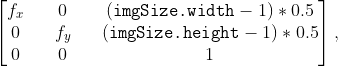
///
/// where  and  are  and  elements of cameraMatrix, respectively.
///
/// By default, the undistortion functions in OpenCV (see #initUndistortRectifyMap, #undistort) do not
/// move the principal point. However, when you work with stereo, it is important to move the principal
/// points in both views to the same y-coordinate (which is required by most of stereo correspondence
/// algorithms), and may be to the same x-coordinate too. So, you can form the new camera matrix for
/// each view where the principal points are located at the center.
///
/// ## Parameters
/// * cameraMatrix: Input camera matrix.
/// * imgsize: Camera view image size in pixels.
/// * centerPrincipalPoint: Location of the principal point in the new camera matrix. The
/// parameter indicates whether this location should be at the image center or not.
///
/// ## C++ default parameters
/// * imgsize: Size()
/// * center_principal_point: false
pub fn get_default_new_camera_matrix(camera_matrix: &dyn core::ToInputArray, imgsize: core::Size, center_principal_point: bool) -> Result<core::Mat> {
input_array_arg!(camera_matrix);
unsafe { sys::cv_getDefaultNewCameraMatrix__InputArray_Size_bool(camera_matrix.as_raw__InputArray(), imgsize, center_principal_point) }.into_result().map(|ptr| core::Mat { ptr })
}
/// Returns filter coefficients for computing spatial image derivatives.
///
/// The function computes and returns the filter coefficients for spatial image derivatives. When
/// `ksize=CV_SCHARR`, the Scharr  kernels are generated (see #Scharr). Otherwise, Sobel
/// kernels are generated (see #Sobel). The filters are normally passed to #sepFilter2D or to
///
/// ## Parameters
/// * kx: Output matrix of row filter coefficients. It has the type ktype .
/// * ky: Output matrix of column filter coefficients. It has the type ktype .
/// * dx: Derivative order in respect of x.
/// * dy: Derivative order in respect of y.
/// * ksize: Aperture size. It can be CV_SCHARR, 1, 3, 5, or 7.
/// * normalize: Flag indicating whether to normalize (scale down) the filter coefficients or not.
/// Theoretically, the coefficients should have the denominator . If you are
/// going to filter floating-point images, you are likely to use the normalized kernels. But if you
/// compute derivatives of an 8-bit image, store the results in a 16-bit image, and wish to preserve
/// all the fractional bits, you may want to set normalize=false .
/// * ktype: Type of filter coefficients. It can be CV_32f or CV_64F .
///
/// ## C++ default parameters
/// * normalize: false
/// * ktype: CV_32F
pub fn get_deriv_kernels(kx: &mut dyn core::ToOutputArray, ky: &mut dyn core::ToOutputArray, dx: i32, dy: i32, ksize: i32, normalize: bool, ktype: i32) -> Result<()> {
output_array_arg!(kx);
output_array_arg!(ky);
unsafe { sys::cv_getDerivKernels__OutputArray__OutputArray_int_int_int_bool_int(kx.as_raw__OutputArray(), ky.as_raw__OutputArray(), dx, dy, ksize, normalize, ktype) }.into_result()
}
/// Calculates the font-specific size to use to achieve a given height in pixels.
///
/// ## Parameters
/// * fontFace: Font to use, see cv::HersheyFonts.
/// * pixelHeight: Pixel height to compute the fontScale for
/// * thickness: Thickness of lines used to render the text.See putText for details.
/// ## Returns
/// The fontSize to use for cv::putText
///
/// @see cv::putText
///
/// ## C++ default parameters
/// * thickness: 1
pub fn get_font_scale_from_height(font_face: i32, pixel_height: i32, thickness: i32) -> Result<f64> {
unsafe { sys::cv_getFontScaleFromHeight_int_int_int(font_face, pixel_height, thickness) }.into_result()
}
/// Returns Gabor filter coefficients.
///
/// For more details about gabor filter equations and parameters, see: [Gabor
/// Filter](http://en.wikipedia.org/wiki/Gabor_filter).
///
/// ## Parameters
/// * ksize: Size of the filter returned.
/// * sigma: Standard deviation of the gaussian envelope.
/// * theta: Orientation of the normal to the parallel stripes of a Gabor function.
/// * lambd: Wavelength of the sinusoidal factor.
/// * gamma: Spatial aspect ratio.
/// * psi: Phase offset.
/// * ktype: Type of filter coefficients. It can be CV_32F or CV_64F .
///
/// ## C++ default parameters
/// * psi: CV_PI*0.5
/// * ktype: CV_64F
pub fn get_gabor_kernel(ksize: core::Size, sigma: f64, theta: f64, lambd: f64, gamma: f64, psi: f64, ktype: i32) -> Result<core::Mat> {
unsafe { sys::cv_getGaborKernel_Size_double_double_double_double_double_int(ksize, sigma, theta, lambd, gamma, psi, ktype) }.into_result().map(|ptr| core::Mat { ptr })
}
/// Returns Gaussian filter coefficients.
///
/// The function computes and returns the  matrix of Gaussian filter
/// coefficients:
///
/// 
///
/// where  and  is the scale factor chosen so that .
///
/// Two of such generated kernels can be passed to sepFilter2D. Those functions automatically recognize
/// smoothing kernels (a symmetrical kernel with sum of weights equal to 1) and handle them accordingly.
/// You may also use the higher-level GaussianBlur.
/// ## Parameters
/// * ksize: Aperture size. It should be odd (  ) and positive.
/// * sigma: Gaussian standard deviation. If it is non-positive, it is computed from ksize as
/// `sigma = 0.3*((ksize-1)*0.5 - 1) + 0.8`.
/// * ktype: Type of filter coefficients. It can be CV_32F or CV_64F .
/// ## See also
/// sepFilter2D, getDerivKernels, getStructuringElement, GaussianBlur
///
/// ## C++ default parameters
/// * ktype: CV_64F
pub fn get_gaussian_kernel(ksize: i32, sigma: f64, ktype: i32) -> Result<core::Mat> {
unsafe { sys::cv_getGaussianKernel_int_double_int(ksize, sigma, ktype) }.into_result().map(|ptr| core::Mat { ptr })
}
/// Calculates a perspective transform from four pairs of the corresponding points.
///
/// The function calculates the  matrix of a perspective transform so that:
///
/// 
///
/// where
///
/// 
///
/// ## Parameters
/// * src: Coordinates of quadrangle vertices in the source image.
/// * dst: Coordinates of the corresponding quadrangle vertices in the destination image.
///
/// ## See also
/// findHomography, warpPerspective, perspectiveTransform
pub fn get_perspective_transform(src: &dyn core::ToInputArray, dst: &dyn core::ToInputArray) -> Result<core::Mat> {
input_array_arg!(src);
input_array_arg!(dst);
unsafe { sys::cv_getPerspectiveTransform__InputArray__InputArray(src.as_raw__InputArray(), dst.as_raw__InputArray()) }.into_result().map(|ptr| core::Mat { ptr })
}
/// returns 3x3 perspective transformation for the corresponding 4 point pairs.
pub fn get_perspective_transform_slice(src: &[core::Point2f], dst: &[core::Point2f]) -> Result<core::Mat> {
unsafe { sys::cv_getPerspectiveTransform_const_Point2f_X_const_Point2f_X(src.as_ptr(), dst.as_ptr()) }.into_result().map(|ptr| core::Mat { ptr })
}
/// Retrieves a pixel rectangle from an image with sub-pixel accuracy.
///
/// The function getRectSubPix extracts pixels from src:
///
/// 
///
/// where the values of the pixels at non-integer coordinates are retrieved using bilinear
/// interpolation. Every channel of multi-channel images is processed independently. Also
/// the image should be a single channel or three channel image. While the center of the
/// rectangle must be inside the image, parts of the rectangle may be outside.
///
/// ## Parameters
/// * image: Source image.
/// * patchSize: Size of the extracted patch.
/// * center: Floating point coordinates of the center of the extracted rectangle within the
/// source image. The center must be inside the image.
/// * patch: Extracted patch that has the size patchSize and the same number of channels as src .
/// * patchType: Depth of the extracted pixels. By default, they have the same depth as src .
///
/// ## See also
/// warpAffine, warpPerspective
///
/// ## C++ default parameters
/// * patch_type: -1
pub fn get_rect_sub_pix(image: &dyn core::ToInputArray, patch_size: core::Size, center: core::Point2f, patch: &mut dyn core::ToOutputArray, patch_type: i32) -> Result<()> {
input_array_arg!(image);
output_array_arg!(patch);
unsafe { sys::cv_getRectSubPix__InputArray_Size_Point2f__OutputArray_int(image.as_raw__InputArray(), patch_size, center, patch.as_raw__OutputArray(), patch_type) }.into_result()
}
/// Calculates an affine matrix of 2D rotation.
///
/// The function calculates the following matrix:
///
/// 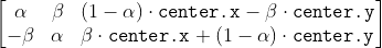
///
/// where
///
/// 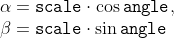
///
/// The transformation maps the rotation center to itself. If this is not the target, adjust the shift.
///
/// ## Parameters
/// * center: Center of the rotation in the source image.
/// * angle: Rotation angle in degrees. Positive values mean counter-clockwise rotation (the
/// coordinate origin is assumed to be the top-left corner).
/// * scale: Isotropic scale factor.
///
/// ## See also
/// getAffineTransform, warpAffine, transform
pub fn get_rotation_matrix_2d(center: core::Point2f, angle: f64, scale: f64) -> Result<core::Mat> {
unsafe { sys::cv_getRotationMatrix2D_Point2f_double_double(center, angle, scale) }.into_result().map(|ptr| core::Mat { ptr })
}
/// Returns a structuring element of the specified size and shape for morphological operations.
///
/// The function constructs and returns the structuring element that can be further passed to #erode,
/// #dilate or #morphologyEx. But you can also construct an arbitrary binary mask yourself and use it as
/// the structuring element.
///
/// ## Parameters
/// * shape: Element shape that could be one of #MorphShapes
/// * ksize: Size of the structuring element.
/// * anchor: Anchor position within the element. The default value  means that the
/// anchor is at the center. Note that only the shape of a cross-shaped element depends on the anchor
/// position. In other cases the anchor just regulates how much the result of the morphological
/// operation is shifted.
///
/// ## C++ default parameters
/// * anchor: Point(-1,-1)
pub fn get_structuring_element(shape: i32, ksize: core::Size, anchor: core::Point) -> Result<core::Mat> {
unsafe { sys::cv_getStructuringElement_int_Size_Point(shape, ksize, anchor) }.into_result().map(|ptr| core::Mat { ptr })
}
/// Calculates the width and height of a text string.
///
/// The function cv::getTextSize calculates and returns the size of a box that contains the specified text.
/// That is, the following code renders some text, the tight box surrounding it, and the baseline: :
/// ```ignore
/// String text = "Funny text inside the box";
/// int fontFace = FONT_HERSHEY_SCRIPT_SIMPLEX;
/// double fontScale = 2;
/// int thickness = 3;
///
/// Mat img(600, 800, CV_8UC3, Scalar::all(0));
///
/// int baseline=0;
/// Size textSize = getTextSize(text, fontFace,
/// fontScale, thickness, &baseline);
/// baseline += thickness;
///
/// // center the text
/// Point textOrg((img.cols - textSize.width)/2,
/// (img.rows + textSize.height)/2);
///
/// // draw the box
/// rectangle(img, textOrg + Point(0, baseline),
/// textOrg + Point(textSize.width, -textSize.height),
/// Scalar(0,0,255));
/// // ... and the baseline first
/// line(img, textOrg + Point(0, thickness),
/// textOrg + Point(textSize.width, thickness),
/// Scalar(0, 0, 255));
///
/// // then put the text itself
/// putText(img, text, textOrg, fontFace, fontScale,
/// Scalar::all(255), thickness, 8);
/// ```
///
///
/// ## Parameters
/// * text: Input text string.
/// * fontFace: Font to use, see #HersheyFonts.
/// * fontScale: Font scale factor that is multiplied by the font-specific base size.
/// * thickness: Thickness of lines used to render the text. See #putText for details.
/// * baseLine: [out] y-coordinate of the baseline relative to the bottom-most text
/// point.
/// ## Returns
/// The size of a box that contains the specified text.
///
/// @see putText
pub fn get_text_size(text: &str, font_face: i32, font_scale: f64, thickness: i32, base_line: &mut i32) -> Result<core::Size> {
string_arg!(text);
unsafe { sys::cv_getTextSize_String_int_double_int_int_X(text.as_ptr(), font_face, font_scale, thickness, base_line) }.into_result()
}
/// Determines strong corners on an image.
///
/// The function finds the most prominent corners in the image or in the specified image region, as
/// described in [Shi94](https://docs.opencv.org/3.4.7/d0/de3/citelist.html#CITEREF_Shi94)
///
/// * Function calculates the corner quality measure at every source image pixel using the
/// #cornerMinEigenVal or #cornerHarris .
/// * Function performs a non-maximum suppression (the local maximums in *3 x 3* neighborhood are
/// retained).
/// * The corners with the minimal eigenvalue less than
///  are rejected.
/// * The remaining corners are sorted by the quality measure in the descending order.
/// * Function throws away each corner for which there is a stronger corner at a distance less than
/// maxDistance.
///
/// The function can be used to initialize a point-based tracker of an object.
///
///
/// Note: If the function is called with different values A and B of the parameter qualityLevel , and
/// A \> B, the vector of returned corners with qualityLevel=A will be the prefix of the output vector
/// with qualityLevel=B .
///
/// ## Parameters
/// * image: Input 8-bit or floating-point 32-bit, single-channel image.
/// * corners: Output vector of detected corners.
/// * maxCorners: Maximum number of corners to return. If there are more corners than are found,
/// the strongest of them is returned. `maxCorners <= 0` implies that no limit on the maximum is set
/// and all detected corners are returned.
/// * qualityLevel: Parameter characterizing the minimal accepted quality of image corners. The
/// parameter value is multiplied by the best corner quality measure, which is the minimal eigenvalue
/// (see #cornerMinEigenVal ) or the Harris function response (see #cornerHarris ). The corners with the
/// quality measure less than the product are rejected. For example, if the best corner has the
/// quality measure = 1500, and the qualityLevel=0.01 , then all the corners with the quality measure
/// less than 15 are rejected.
/// * minDistance: Minimum possible Euclidean distance between the returned corners.
/// * mask: Optional region of interest. If the image is not empty (it needs to have the type
/// CV_8UC1 and the same size as image ), it specifies the region in which the corners are detected.
/// * blockSize: Size of an average block for computing a derivative covariation matrix over each
/// pixel neighborhood. See cornerEigenValsAndVecs .
/// * useHarrisDetector: Parameter indicating whether to use a Harris detector (see #cornerHarris)
/// or #cornerMinEigenVal.
/// * k: Free parameter of the Harris detector.
///
/// ## See also
/// cornerMinEigenVal, cornerHarris, calcOpticalFlowPyrLK, estimateRigidTransform,
///
/// ## C++ default parameters
/// * mask: noArray()
/// * block_size: 3
/// * use_harris_detector: false
/// * k: 0.04
pub fn good_features_to_track(image: &dyn core::ToInputArray, corners: &mut dyn core::ToOutputArray, max_corners: i32, quality_level: f64, min_distance: f64, mask: &dyn core::ToInputArray, block_size: i32, use_harris_detector: bool, k: f64) -> Result<()> {
input_array_arg!(image);
output_array_arg!(corners);
input_array_arg!(mask);
unsafe { sys::cv_goodFeaturesToTrack__InputArray__OutputArray_int_double_double__InputArray_int_bool_double(image.as_raw__InputArray(), corners.as_raw__OutputArray(), max_corners, quality_level, min_distance, mask.as_raw__InputArray(), block_size, use_harris_detector, k) }.into_result()
}
///
/// ## C++ default parameters
/// * use_harris_detector: false
/// * k: 0.04
pub fn good_features_to_track_with_gradient(image: &dyn core::ToInputArray, corners: &mut dyn core::ToOutputArray, max_corners: i32, quality_level: f64, min_distance: f64, mask: &dyn core::ToInputArray, block_size: i32, gradient_size: i32, use_harris_detector: bool, k: f64) -> Result<()> {
input_array_arg!(image);
output_array_arg!(corners);
input_array_arg!(mask);
unsafe { sys::cv_goodFeaturesToTrack__InputArray__OutputArray_int_double_double__InputArray_int_int_bool_double(image.as_raw__InputArray(), corners.as_raw__OutputArray(), max_corners, quality_level, min_distance, mask.as_raw__InputArray(), block_size, gradient_size, use_harris_detector, k) }.into_result()
}
/// Runs the GrabCut algorithm.
///
/// The function implements the [GrabCut image segmentation algorithm](http://en.wikipedia.org/wiki/GrabCut).
///
/// ## Parameters
/// * img: Input 8-bit 3-channel image.
/// * mask: Input/output 8-bit single-channel mask. The mask is initialized by the function when
/// mode is set to #GC_INIT_WITH_RECT. Its elements may have one of the #GrabCutClasses.
/// * rect: ROI containing a segmented object. The pixels outside of the ROI are marked as
/// "obvious background". The parameter is only used when mode==#GC_INIT_WITH_RECT .
/// * bgdModel: Temporary array for the background model. Do not modify it while you are
/// processing the same image.
/// * fgdModel: Temporary arrays for the foreground model. Do not modify it while you are
/// processing the same image.
/// * iterCount: Number of iterations the algorithm should make before returning the result. Note
/// that the result can be refined with further calls with mode==#GC_INIT_WITH_MASK or
/// mode==GC_EVAL .
/// * mode: Operation mode that could be one of the #GrabCutModes
///
/// ## C++ default parameters
/// * mode: GC_EVAL
pub fn grab_cut(img: &dyn core::ToInputArray, mask: &mut dyn core::ToInputOutputArray, rect: core::Rect, bgd_model: &mut dyn core::ToInputOutputArray, fgd_model: &mut dyn core::ToInputOutputArray, iter_count: i32, mode: i32) -> Result<()> {
input_array_arg!(img);
input_output_array_arg!(mask);
input_output_array_arg!(bgd_model);
input_output_array_arg!(fgd_model);
unsafe { sys::cv_grabCut__InputArray__InputOutputArray_Rect__InputOutputArray__InputOutputArray_int_int(img.as_raw__InputArray(), mask.as_raw__InputOutputArray(), rect, bgd_model.as_raw__InputOutputArray(), fgd_model.as_raw__InputOutputArray(), iter_count, mode) }.into_result()
}
/// Computes the undistortion and rectification transformation map.
///
/// The function computes the joint undistortion and rectification transformation and represents the
/// result in the form of maps for remap. The undistorted image looks like original, as if it is
/// captured with a camera using the camera matrix =newCameraMatrix and zero distortion. In case of a
/// monocular camera, newCameraMatrix is usually equal to cameraMatrix, or it can be computed by
/// #getOptimalNewCameraMatrix for a better control over scaling. In case of a stereo camera,
/// newCameraMatrix is normally set to P1 or P2 computed by #stereoRectify .
///
/// Also, this new camera is oriented differently in the coordinate space, according to R. That, for
/// example, helps to align two heads of a stereo camera so that the epipolar lines on both images
/// become horizontal and have the same y- coordinate (in case of a horizontally aligned stereo camera).
///
/// The function actually builds the maps for the inverse mapping algorithm that is used by remap. That
/// is, for each pixel  in the destination (corrected and rectified) image, the function
/// computes the corresponding coordinates in the source image (that is, in the original image from
/// camera). The following process is applied:
/// 
/// where 
/// are the distortion coefficients.
///
/// In case of a stereo camera, this function is called twice: once for each camera head, after
/// stereoRectify, which in its turn is called after #stereoCalibrate. But if the stereo camera
/// was not calibrated, it is still possible to compute the rectification transformations directly from
/// the fundamental matrix using #stereoRectifyUncalibrated. For each camera, the function computes
/// homography H as the rectification transformation in a pixel domain, not a rotation matrix R in 3D
/// space. R can be computed from H as
/// 
/// where cameraMatrix can be chosen arbitrarily.
///
/// ## Parameters
/// * cameraMatrix: Input camera matrix  .
/// * distCoeffs: Input vector of distortion coefficients
/// 
/// of 4, 5, 8, 12 or 14 elements. If the vector is NULL/empty, the zero distortion coefficients are assumed.
/// * R: Optional rectification transformation in the object space (3x3 matrix). R1 or R2 ,
/// computed by #stereoRectify can be passed here. If the matrix is empty, the identity transformation
/// is assumed. In cvInitUndistortMap R assumed to be an identity matrix.
/// * newCameraMatrix: New camera matrix 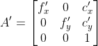.
/// * size: Undistorted image size.
/// * m1type: Type of the first output map that can be CV_32FC1, CV_32FC2 or CV_16SC2, see #convertMaps
/// * map1: The first output map.
/// * map2: The second output map.
pub fn init_undistort_rectify_map(camera_matrix: &dyn core::ToInputArray, dist_coeffs: &dyn core::ToInputArray, r: &dyn core::ToInputArray, new_camera_matrix: &dyn core::ToInputArray, size: core::Size, m1type: i32, map1: &mut dyn core::ToOutputArray, map2: &mut dyn core::ToOutputArray) -> Result<()> {
input_array_arg!(camera_matrix);
input_array_arg!(dist_coeffs);
input_array_arg!(r);
input_array_arg!(new_camera_matrix);
output_array_arg!(map1);
output_array_arg!(map2);
unsafe { sys::cv_initUndistortRectifyMap__InputArray__InputArray__InputArray__InputArray_Size_int__OutputArray__OutputArray(camera_matrix.as_raw__InputArray(), dist_coeffs.as_raw__InputArray(), r.as_raw__InputArray(), new_camera_matrix.as_raw__InputArray(), size, m1type, map1.as_raw__OutputArray(), map2.as_raw__OutputArray()) }.into_result()
}
/// initializes maps for #remap for wide-angle
///
/// ## C++ default parameters
/// * proj_type: PROJ_SPHERICAL_EQRECT
/// * alpha: 0
pub fn init_wide_angle_proj_map_with_type_i32(camera_matrix: &dyn core::ToInputArray, dist_coeffs: &dyn core::ToInputArray, image_size: core::Size, dest_image_width: i32, m1type: i32, map1: &mut dyn core::ToOutputArray, map2: &mut dyn core::ToOutputArray, proj_type: i32, alpha: f64) -> Result<f32> {
input_array_arg!(camera_matrix);
input_array_arg!(dist_coeffs);
output_array_arg!(map1);
output_array_arg!(map2);
unsafe { sys::cv_initWideAngleProjMap__InputArray__InputArray_Size_int_int__OutputArray__OutputArray_int_double(camera_matrix.as_raw__InputArray(), dist_coeffs.as_raw__InputArray(), image_size, dest_image_width, m1type, map1.as_raw__OutputArray(), map2.as_raw__OutputArray(), proj_type, alpha) }.into_result()
}
/// Calculates the integral of an image.
///
/// The function calculates one or more integral images for the source image as follows:
///
/// 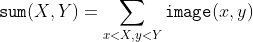
///
/// 
///
/// 
///
/// Using these integral images, you can calculate sum, mean, and standard deviation over a specific
/// up-right or rotated rectangular region of the image in a constant time, for example:
///
/// 
///
/// It makes possible to do a fast blurring or fast block correlation with a variable window size, for
/// example. In case of multi-channel images, sums for each channel are accumulated independently.
///
/// As a practical example, the next figure shows the calculation of the integral of a straight
/// rectangle Rect(3,3,3,2) and of a tilted rectangle Rect(5,1,2,3) . The selected pixels in the
/// original image are shown, as well as the relative pixels in the integral images sum and tilted .
///
/// 
///
/// ## Parameters
/// * src: input image as , 8-bit or floating-point (32f or 64f).
/// * sum: integral image as  , 32-bit integer or floating-point (32f or 64f).
/// * sqsum: integral image for squared pixel values; it is , double-precision
/// floating-point (64f) array.
/// * tilted: integral for the image rotated by 45 degrees; it is  array with
/// the same data type as sum.
/// * sdepth: desired depth of the integral and the tilted integral images, CV_32S, CV_32F, or
/// CV_64F.
/// * sqdepth: desired depth of the integral image of squared pixel values, CV_32F or CV_64F.
///
/// ## C++ default parameters
/// * sdepth: -1
/// * sqdepth: -1
pub fn integral_titled_sq(src: &dyn core::ToInputArray, sum: &mut dyn core::ToOutputArray, sqsum: &mut dyn core::ToOutputArray, tilted: &mut dyn core::ToOutputArray, sdepth: i32, sqdepth: i32) -> Result<()> {
input_array_arg!(src);
output_array_arg!(sum);
output_array_arg!(sqsum);
output_array_arg!(tilted);
unsafe { sys::cv_integral__InputArray__OutputArray__OutputArray__OutputArray_int_int(src.as_raw__InputArray(), sum.as_raw__OutputArray(), sqsum.as_raw__OutputArray(), tilted.as_raw__OutputArray(), sdepth, sqdepth) }.into_result()
}
/// Calculates the integral of an image.
///
/// The function calculates one or more integral images for the source image as follows:
///
/// 
///
/// 
///
/// 
///
/// Using these integral images, you can calculate sum, mean, and standard deviation over a specific
/// up-right or rotated rectangular region of the image in a constant time, for example:
///
/// 
///
/// It makes possible to do a fast blurring or fast block correlation with a variable window size, for
/// example. In case of multi-channel images, sums for each channel are accumulated independently.
///
/// As a practical example, the next figure shows the calculation of the integral of a straight
/// rectangle Rect(3,3,3,2) and of a tilted rectangle Rect(5,1,2,3) . The selected pixels in the
/// original image are shown, as well as the relative pixels in the integral images sum and tilted .
///
/// 
///
/// ## Parameters
/// * src: input image as , 8-bit or floating-point (32f or 64f).
/// * sum: integral image as  , 32-bit integer or floating-point (32f or 64f).
/// * sqsum: integral image for squared pixel values; it is , double-precision
/// floating-point (64f) array.
/// * tilted: integral for the image rotated by 45 degrees; it is  array with
/// the same data type as sum.
/// * sdepth: desired depth of the integral and the tilted integral images, CV_32S, CV_32F, or
/// CV_64F.
/// * sqdepth: desired depth of the integral image of squared pixel values, CV_32F or CV_64F.
///
/// ## Overloaded parameters
///
/// ## C++ default parameters
/// * sdepth: -1
/// * sqdepth: -1
pub fn integral_sq_depth(src: &dyn core::ToInputArray, sum: &mut dyn core::ToOutputArray, sqsum: &mut dyn core::ToOutputArray, sdepth: i32, sqdepth: i32) -> Result<()> {
input_array_arg!(src);
output_array_arg!(sum);
output_array_arg!(sqsum);
unsafe { sys::cv_integral__InputArray__OutputArray__OutputArray_int_int(src.as_raw__InputArray(), sum.as_raw__OutputArray(), sqsum.as_raw__OutputArray(), sdepth, sqdepth) }.into_result()
}
/// Calculates the integral of an image.
///
/// The function calculates one or more integral images for the source image as follows:
///
/// 
///
/// 
///
/// 
///
/// Using these integral images, you can calculate sum, mean, and standard deviation over a specific
/// up-right or rotated rectangular region of the image in a constant time, for example:
///
/// 
///
/// It makes possible to do a fast blurring or fast block correlation with a variable window size, for
/// example. In case of multi-channel images, sums for each channel are accumulated independently.
///
/// As a practical example, the next figure shows the calculation of the integral of a straight
/// rectangle Rect(3,3,3,2) and of a tilted rectangle Rect(5,1,2,3) . The selected pixels in the
/// original image are shown, as well as the relative pixels in the integral images sum and tilted .
///
/// 
///
/// ## Parameters
/// * src: input image as , 8-bit or floating-point (32f or 64f).
/// * sum: integral image as  , 32-bit integer or floating-point (32f or 64f).
/// * sqsum: integral image for squared pixel values; it is , double-precision
/// floating-point (64f) array.
/// * tilted: integral for the image rotated by 45 degrees; it is  array with
/// the same data type as sum.
/// * sdepth: desired depth of the integral and the tilted integral images, CV_32S, CV_32F, or
/// CV_64F.
/// * sqdepth: desired depth of the integral image of squared pixel values, CV_32F or CV_64F.
///
/// ## Overloaded parameters
///
/// ## C++ default parameters
/// * sdepth: -1
pub fn integral(src: &dyn core::ToInputArray, sum: &mut dyn core::ToOutputArray, sdepth: i32) -> Result<()> {
input_array_arg!(src);
output_array_arg!(sum);
unsafe { sys::cv_integral__InputArray__OutputArray_int(src.as_raw__InputArray(), sum.as_raw__OutputArray(), sdepth) }.into_result()
}
/// finds intersection of two convex polygons
///
/// ## C++ default parameters
/// * handle_nested: true
pub fn intersect_convex_convex(_p1: &dyn core::ToInputArray, _p2: &dyn core::ToInputArray, _p12: &mut dyn core::ToOutputArray, handle_nested: bool) -> Result<f32> {
input_array_arg!(_p1);
input_array_arg!(_p2);
output_array_arg!(_p12);
unsafe { sys::cv_intersectConvexConvex__InputArray__InputArray__OutputArray_bool(_p1.as_raw__InputArray(), _p2.as_raw__InputArray(), _p12.as_raw__OutputArray(), handle_nested) }.into_result()
}
/// Inverts an affine transformation.
///
/// The function computes an inverse affine transformation represented by  matrix M:
///
/// 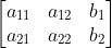
///
/// The result is also a  matrix of the same type as M.
///
/// ## Parameters
/// * M: Original affine transformation.
/// * iM: Output reverse affine transformation.
pub fn invert_affine_transform(m: &dyn core::ToInputArray, i_m: &mut dyn core::ToOutputArray) -> Result<()> {
input_array_arg!(m);
output_array_arg!(i_m);
unsafe { sys::cv_invertAffineTransform__InputArray__OutputArray(m.as_raw__InputArray(), i_m.as_raw__OutputArray()) }.into_result()
}
/// Tests a contour convexity.
///
/// The function tests whether the input contour is convex or not. The contour must be simple, that is,
/// without self-intersections. Otherwise, the function output is undefined.
///
/// ## Parameters
/// * contour: Input vector of 2D points, stored in std::vector\<\> or Mat
pub fn is_contour_convex(contour: &dyn core::ToInputArray) -> Result<bool> {
input_array_arg!(contour);
unsafe { sys::cv_isContourConvex__InputArray(contour.as_raw__InputArray()) }.into_result()
}
/// Draws a line segment connecting two points.
///
/// The function line draws the line segment between pt1 and pt2 points in the image. The line is
/// clipped by the image boundaries. For non-antialiased lines with integer coordinates, the 8-connected
/// or 4-connected Bresenham algorithm is used. Thick lines are drawn with rounding endings. Antialiased
/// lines are drawn using Gaussian filtering.
///
/// ## Parameters
/// * img: Image.
/// * pt1: First point of the line segment.
/// * pt2: Second point of the line segment.
/// * color: Line color.
/// * thickness: Line thickness.
/// * lineType: Type of the line. See #LineTypes.
/// * shift: Number of fractional bits in the point coordinates.
///
/// ## C++ default parameters
/// * thickness: 1
/// * line_type: LINE_8
/// * shift: 0
pub fn line(img: &mut dyn core::ToInputOutputArray, pt1: core::Point, pt2: core::Point, color: core::Scalar, thickness: i32, line_type: i32, shift: i32) -> Result<()> {
input_output_array_arg!(img);
unsafe { sys::cv_line__InputOutputArray_Point_Point_Scalar_int_int_int(img.as_raw__InputOutputArray(), pt1, pt2, color, thickness, line_type, shift) }.into_result()
}
/// Remaps an image to polar coordinates space.
///
/// **Deprecated**: This function produces same result as cv::warpPolar(src, dst, src.size(), center, maxRadius, flags)
///
///
/// @internal
/// Transform the source image using the following transformation (See @ref polar_remaps_reference_image "Polar remaps reference image c)"):
/// 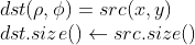
///
/// where
/// 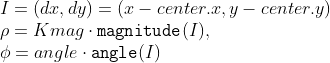
///
/// and
/// 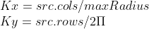
///
///
/// ## Parameters
/// * src: Source image
/// * dst: Destination image. It will have same size and type as src.
/// * center: The transformation center;
/// * maxRadius: The radius of the bounding circle to transform. It determines the inverse magnitude scale parameter too.
/// * flags: A combination of interpolation methods, see #InterpolationFlags
///
///
/// Note:
/// * The function can not operate in-place.
/// * To calculate magnitude and angle in degrees #cartToPolar is used internally thus angles are measured from 0 to 360 with accuracy about 0.3 degrees.
///
/// ## See also
/// cv::logPolar
/// @endinternal
#[deprecated = "This function produces same result as cv::warpPolar(src, dst, src.size(), center, maxRadius, flags)"]
pub fn linear_polar(src: &dyn core::ToInputArray, dst: &mut dyn core::ToOutputArray, center: core::Point2f, max_radius: f64, flags: i32) -> Result<()> {
input_array_arg!(src);
output_array_arg!(dst);
unsafe { sys::cv_linearPolar__InputArray__OutputArray_Point2f_double_int(src.as_raw__InputArray(), dst.as_raw__OutputArray(), center, max_radius, flags) }.into_result()
}
/// Remaps an image to semilog-polar coordinates space.
///
/// **Deprecated**: This function produces same result as cv::warpPolar(src, dst, src.size(), center, maxRadius, flags+WARP_POLAR_LOG);
///
///
/// @internal
/// Transform the source image using the following transformation (See @ref polar_remaps_reference_image "Polar remaps reference image d)"):
/// 
///
/// where
/// 
///
/// and
/// 
///
/// The function emulates the human "foveal" vision and can be used for fast scale and
/// rotation-invariant template matching, for object tracking and so forth.
/// ## Parameters
/// * src: Source image
/// * dst: Destination image. It will have same size and type as src.
/// * center: The transformation center; where the output precision is maximal
/// * M: Magnitude scale parameter. It determines the radius of the bounding circle to transform too.
/// * flags: A combination of interpolation methods, see #InterpolationFlags
///
///
/// Note:
/// * The function can not operate in-place.
/// * To calculate magnitude and angle in degrees #cartToPolar is used internally thus angles are measured from 0 to 360 with accuracy about 0.3 degrees.
///
/// ## See also
/// cv::linearPolar
/// @endinternal
#[deprecated = "This function produces same result as cv::warpPolar(src, dst, src.size(), center, maxRadius, flags+WARP_POLAR_LOG);"]
pub fn log_polar(src: &dyn core::ToInputArray, dst: &mut dyn core::ToOutputArray, center: core::Point2f, m: f64, flags: i32) -> Result<()> {
input_array_arg!(src);
output_array_arg!(dst);
unsafe { sys::cv_logPolar__InputArray__OutputArray_Point2f_double_int(src.as_raw__InputArray(), dst.as_raw__OutputArray(), center, m, flags) }.into_result()
}
/// Compares two shapes.
///
/// The function compares two shapes. All three implemented methods use the Hu invariants (see #HuMoments)
///
/// ## Parameters
/// * contour1: First contour or grayscale image.
/// * contour2: Second contour or grayscale image.
/// * method: Comparison method, see #ShapeMatchModes
/// * parameter: Method-specific parameter (not supported now).
pub fn match_shapes(contour1: &dyn core::ToInputArray, contour2: &dyn core::ToInputArray, method: i32, parameter: f64) -> Result<f64> {
input_array_arg!(contour1);
input_array_arg!(contour2);
unsafe { sys::cv_matchShapes__InputArray__InputArray_int_double(contour1.as_raw__InputArray(), contour2.as_raw__InputArray(), method, parameter) }.into_result()
}
/// Compares a template against overlapped image regions.
///
/// The function slides through image , compares the overlapped patches of size  against
/// templ using the specified method and stores the comparison results in result . Here are the formulae
/// for the available comparison methods (  denotes image,  template,  result ). The summation
/// is done over template and/or the image patch: 
///
/// After the function finishes the comparison, the best matches can be found as global minimums (when
/// #TM_SQDIFF was used) or maximums (when #TM_CCORR or #TM_CCOEFF was used) using the
/// #minMaxLoc function. In case of a color image, template summation in the numerator and each sum in
/// the denominator is done over all of the channels and separate mean values are used for each channel.
/// That is, the function can take a color template and a color image. The result will still be a
/// single-channel image, which is easier to analyze.
///
/// ## Parameters
/// * image: Image where the search is running. It must be 8-bit or 32-bit floating-point.
/// * templ: Searched template. It must be not greater than the source image and have the same
/// data type.
/// * result: Map of comparison results. It must be single-channel 32-bit floating-point. If image
/// is  and templ is  , then result is  .
/// * method: Parameter specifying the comparison method, see #TemplateMatchModes
/// * mask: Mask of searched template. It must have the same datatype and size with templ. It is
/// not set by default. Currently, only the #TM_SQDIFF and #TM_CCORR_NORMED methods are supported.
///
/// ## C++ default parameters
/// * mask: noArray()
pub fn match_template(image: &dyn core::ToInputArray, templ: &dyn core::ToInputArray, result: &mut dyn core::ToOutputArray, method: i32, mask: &dyn core::ToInputArray) -> Result<()> {
input_array_arg!(image);
input_array_arg!(templ);
output_array_arg!(result);
input_array_arg!(mask);
unsafe { sys::cv_matchTemplate__InputArray__InputArray__OutputArray_int__InputArray(image.as_raw__InputArray(), templ.as_raw__InputArray(), result.as_raw__OutputArray(), method, mask.as_raw__InputArray()) }.into_result()
}
/// Blurs an image using the median filter.
///
/// The function smoothes an image using the median filter with the  aperture. Each channel of a multi-channel image is processed independently.
/// In-place operation is supported.
///
///
/// Note: The median filter uses #BORDER_REPLICATE internally to cope with border pixels, see #BorderTypes
///
/// ## Parameters
/// * src: input 1-, 3-, or 4-channel image; when ksize is 3 or 5, the image depth should be
/// CV_8U, CV_16U, or CV_32F, for larger aperture sizes, it can only be CV_8U.
/// * dst: destination array of the same size and type as src.
/// * ksize: aperture linear size; it must be odd and greater than 1, for example: 3, 5, 7 ...
/// ## See also
/// bilateralFilter, blur, boxFilter, GaussianBlur
pub fn median_blur(src: &dyn core::ToInputArray, dst: &mut dyn core::ToOutputArray, ksize: i32) -> Result<()> {
input_array_arg!(src);
output_array_arg!(dst);
unsafe { sys::cv_medianBlur__InputArray__OutputArray_int(src.as_raw__InputArray(), dst.as_raw__OutputArray(), ksize) }.into_result()
}
/// Finds a rotated rectangle of the minimum area enclosing the input 2D point set.
///
/// The function calculates and returns the minimum-area bounding rectangle (possibly rotated) for a
/// specified point set. Developer should keep in mind that the returned RotatedRect can contain negative
/// indices when data is close to the containing Mat element boundary.
///
/// ## Parameters
/// * points: Input vector of 2D points, stored in std::vector\<\> or Mat
pub fn min_area_rect(points: &dyn core::ToInputArray) -> Result<core::RotatedRect> {
input_array_arg!(points);
unsafe { sys::cv_minAreaRect__InputArray(points.as_raw__InputArray()) }.into_result().map(|ptr| core::RotatedRect { ptr })
}
/// Finds a circle of the minimum area enclosing a 2D point set.
///
/// The function finds the minimal enclosing circle of a 2D point set using an iterative algorithm.
///
/// ## Parameters
/// * points: Input vector of 2D points, stored in std::vector\<\> or Mat
/// * center: Output center of the circle.
/// * radius: Output radius of the circle.
pub fn min_enclosing_circle(points: &dyn core::ToInputArray, center: &mut core::Point2f, radius: &mut f32) -> Result<()> {
input_array_arg!(points);
unsafe { sys::cv_minEnclosingCircle__InputArray_Point2f_float(points.as_raw__InputArray(), center, radius) }.into_result()
}
/// Finds a triangle of minimum area enclosing a 2D point set and returns its area.
///
/// The function finds a triangle of minimum area enclosing the given set of 2D points and returns its
/// area. The output for a given 2D point set is shown in the image below. 2D points are depicted in
/// *red* and the enclosing triangle in *yellow*.
///
/// 
///
/// The implementation of the algorithm is based on O'Rourke's [ORourke86](https://docs.opencv.org/3.4.7/d0/de3/citelist.html#CITEREF_ORourke86) and Klee and Laskowski's
/// [KleeLaskowski85](https://docs.opencv.org/3.4.7/d0/de3/citelist.html#CITEREF_KleeLaskowski85) papers. O'Rourke provides a  algorithm for finding the minimal
/// enclosing triangle of a 2D convex polygon with n vertices. Since the #minEnclosingTriangle function
/// takes a 2D point set as input an additional preprocessing step of computing the convex hull of the
/// 2D point set is required. The complexity of the #convexHull function is  which is higher
/// than . Thus the overall complexity of the function is .
///
/// ## Parameters
/// * points: Input vector of 2D points with depth CV_32S or CV_32F, stored in std::vector\<\> or Mat
/// * triangle: Output vector of three 2D points defining the vertices of the triangle. The depth
/// of the OutputArray must be CV_32F.
pub fn min_enclosing_triangle(points: &dyn core::ToInputArray, triangle: &mut dyn core::ToOutputArray) -> Result<f64> {
input_array_arg!(points);
output_array_arg!(triangle);
unsafe { sys::cv_minEnclosingTriangle__InputArray__OutputArray(points.as_raw__InputArray(), triangle.as_raw__OutputArray()) }.into_result()
}
/// returns "magic" border value for erosion and dilation. It is automatically transformed to Scalar::all(-DBL_MAX) for dilation.
pub fn morphology_default_border_value() -> Result<core::Scalar> {
unsafe { sys::cv_morphologyDefaultBorderValue() }.into_result()
}
/// Performs advanced morphological transformations.
///
/// The function cv::morphologyEx can perform advanced morphological transformations using an erosion and dilation as
/// basic operations.
///
/// Any of the operations can be done in-place. In case of multi-channel images, each channel is
/// processed independently.
///
/// ## Parameters
/// * src: Source image. The number of channels can be arbitrary. The depth should be one of
/// CV_8U, CV_16U, CV_16S, CV_32F or CV_64F.
/// * dst: Destination image of the same size and type as source image.
/// * op: Type of a morphological operation, see #MorphTypes
/// * kernel: Structuring element. It can be created using #getStructuringElement.
/// * anchor: Anchor position with the kernel. Negative values mean that the anchor is at the
/// kernel center.
/// * iterations: Number of times erosion and dilation are applied.
/// * borderType: Pixel extrapolation method, see #BorderTypes
/// * borderValue: Border value in case of a constant border. The default value has a special
/// meaning.
/// ## See also
/// dilate, erode, getStructuringElement
///
/// Note: The number of iterations is the number of times erosion or dilatation operation will be applied.
/// For instance, an opening operation (#MORPH_OPEN) with two iterations is equivalent to apply
/// successively: erode -> erode -> dilate -> dilate (and not erode -> dilate -> erode -> dilate).
///
/// ## C++ default parameters
/// * anchor: Point(-1,-1)
/// * iterations: 1
/// * border_type: BORDER_CONSTANT
/// * border_value: morphologyDefaultBorderValue()
pub fn morphology_ex(src: &dyn core::ToInputArray, dst: &mut dyn core::ToOutputArray, op: i32, kernel: &dyn core::ToInputArray, anchor: core::Point, iterations: i32, border_type: i32, border_value: core::Scalar) -> Result<()> {
input_array_arg!(src);
output_array_arg!(dst);
input_array_arg!(kernel);
unsafe { sys::cv_morphologyEx__InputArray__OutputArray_int__InputArray_Point_int_int_Scalar(src.as_raw__InputArray(), dst.as_raw__OutputArray(), op, kernel.as_raw__InputArray(), anchor, iterations, border_type, border_value) }.into_result()
}
/// The function is used to detect translational shifts that occur between two images.
///
/// The operation takes advantage of the Fourier shift theorem for detecting the translational shift in
/// the frequency domain. It can be used for fast image registration as well as motion estimation. For
/// more information please see <http://en.wikipedia.org/wiki/Phase_correlation>
///
/// Calculates the cross-power spectrum of two supplied source arrays. The arrays are padded if needed
/// with getOptimalDFTSize.
///
/// The function performs the following equations:
/// - First it applies a Hanning window (see <http://en.wikipedia.org/wiki/Hann_function>) to each
/// image to remove possible edge effects. This window is cached until the array size changes to speed
/// up processing time.
/// - Next it computes the forward DFTs of each source array:
/// 
/// where  is the forward DFT.
/// - It then computes the cross-power spectrum of each frequency domain array:
/// 
/// - Next the cross-correlation is converted back into the time domain via the inverse DFT:
/// 
/// - Finally, it computes the peak location and computes a 5x5 weighted centroid around the peak to
/// achieve sub-pixel accuracy.
/// 
/// - If non-zero, the response parameter is computed as the sum of the elements of r within the 5x5
/// centroid around the peak location. It is normalized to a maximum of 1 (meaning there is a single
/// peak) and will be smaller when there are multiple peaks.
///
/// ## Parameters
/// * src1: Source floating point array (CV_32FC1 or CV_64FC1)
/// * src2: Source floating point array (CV_32FC1 or CV_64FC1)
/// * window: Floating point array with windowing coefficients to reduce edge effects (optional).
/// * response: Signal power within the 5x5 centroid around the peak, between 0 and 1 (optional).
/// ## Returns
/// detected phase shift (sub-pixel) between the two arrays.
///
/// ## See also
/// dft, getOptimalDFTSize, idft, mulSpectrums createHanningWindow
///
/// ## C++ default parameters
/// * window: noArray()
/// * response: 0
pub fn phase_correlate(src1: &dyn core::ToInputArray, src2: &dyn core::ToInputArray, window: &dyn core::ToInputArray, response: &mut f64) -> Result<core::Point2d> {
input_array_arg!(src1);
input_array_arg!(src2);
input_array_arg!(window);
unsafe { sys::cv_phaseCorrelate__InputArray__InputArray__InputArray_double_X(src1.as_raw__InputArray(), src2.as_raw__InputArray(), window.as_raw__InputArray(), response) }.into_result()
}
/// Performs a point-in-contour test.
///
/// The function determines whether the point is inside a contour, outside, or lies on an edge (or
/// coincides with a vertex). It returns positive (inside), negative (outside), or zero (on an edge)
/// value, correspondingly. When measureDist=false , the return value is +1, -1, and 0, respectively.
/// Otherwise, the return value is a signed distance between the point and the nearest contour edge.
///
/// See below a sample output of the function where each image pixel is tested against the contour:
///
/// 
///
/// ## Parameters
/// * contour: Input contour.
/// * pt: Point tested against the contour.
/// * measureDist: If true, the function estimates the signed distance from the point to the
/// nearest contour edge. Otherwise, the function only checks if the point is inside a contour or not.
pub fn point_polygon_test(contour: &dyn core::ToInputArray, pt: core::Point2f, measure_dist: bool) -> Result<f64> {
input_array_arg!(contour);
unsafe { sys::cv_pointPolygonTest__InputArray_Point2f_bool(contour.as_raw__InputArray(), pt, measure_dist) }.into_result()
}
/// Draws several polygonal curves.
///
/// ## Parameters
/// * img: Image.
/// * pts: Array of polygonal curves.
/// * isClosed: Flag indicating whether the drawn polylines are closed or not. If they are closed,
/// the function draws a line from the last vertex of each curve to its first vertex.
/// * color: Polyline color.
/// * thickness: Thickness of the polyline edges.
/// * lineType: Type of the line segments. See #LineTypes
/// * shift: Number of fractional bits in the vertex coordinates.
///
/// The function cv::polylines draws one or more polygonal curves.
///
/// ## C++ default parameters
/// * thickness: 1
/// * line_type: LINE_8
/// * shift: 0
pub fn polylines(img: &mut dyn core::ToInputOutputArray, pts: &dyn core::ToInputArray, is_closed: bool, color: core::Scalar, thickness: i32, line_type: i32, shift: i32) -> Result<()> {
input_output_array_arg!(img);
input_array_arg!(pts);
unsafe { sys::cv_polylines__InputOutputArray__InputArray_bool_Scalar_int_int_int(img.as_raw__InputOutputArray(), pts.as_raw__InputArray(), is_closed, color, thickness, line_type, shift) }.into_result()
}
/// Calculates a feature map for corner detection.
///
/// The function calculates the complex spatial derivative-based function of the source image
///
/// 
///
/// where , are the first image derivatives, , are the second image
/// derivatives, and  is the mixed derivative.
///
/// The corners can be found as local maximums of the functions, as shown below:
/// ```ignore
/// Mat corners, dilated_corners;
/// preCornerDetect(image, corners, 3);
/// // dilation with 3x3 rectangular structuring element
/// dilate(corners, dilated_corners, Mat(), 1);
/// Mat corner_mask = corners == dilated_corners;
/// ```
///
///
/// ## Parameters
/// * src: Source single-channel 8-bit of floating-point image.
/// * dst: Output image that has the type CV_32F and the same size as src .
/// * ksize: %Aperture size of the Sobel .
/// * borderType: Pixel extrapolation method. See #BorderTypes.
///
/// ## C++ default parameters
/// * border_type: BORDER_DEFAULT
pub fn pre_corner_detect(src: &dyn core::ToInputArray, dst: &mut dyn core::ToOutputArray, ksize: i32, border_type: i32) -> Result<()> {
input_array_arg!(src);
output_array_arg!(dst);
unsafe { sys::cv_preCornerDetect__InputArray__OutputArray_int_int(src.as_raw__InputArray(), dst.as_raw__OutputArray(), ksize, border_type) }.into_result()
}
/// Draws a text string.
///
/// The function cv::putText renders the specified text string in the image. Symbols that cannot be rendered
/// using the specified font are replaced by question marks. See #getTextSize for a text rendering code
/// example.
///
/// ## Parameters
/// * img: Image.
/// * text: Text string to be drawn.
/// * org: Bottom-left corner of the text string in the image.
/// * fontFace: Font type, see #HersheyFonts.
/// * fontScale: Font scale factor that is multiplied by the font-specific base size.
/// * color: Text color.
/// * thickness: Thickness of the lines used to draw a text.
/// * lineType: Line type. See #LineTypes
/// * bottomLeftOrigin: When true, the image data origin is at the bottom-left corner. Otherwise,
/// it is at the top-left corner.
///
/// ## C++ default parameters
/// * thickness: 1
/// * line_type: LINE_8
/// * bottom_left_origin: false
pub fn put_text(img: &mut dyn core::ToInputOutputArray, text: &str, org: core::Point, font_face: i32, font_scale: f64, color: core::Scalar, thickness: i32, line_type: i32, bottom_left_origin: bool) -> Result<()> {
input_output_array_arg!(img);
string_arg!(text);
unsafe { sys::cv_putText__InputOutputArray_String_Point_int_double_Scalar_int_int_bool(img.as_raw__InputOutputArray(), text.as_ptr(), org, font_face, font_scale, color, thickness, line_type, bottom_left_origin) }.into_result()
}
/// Blurs an image and downsamples it.
///
/// By default, size of the output image is computed as `Size((src.cols+1)/2, (src.rows+1)/2)`, but in
/// any case, the following conditions should be satisfied:
///
/// 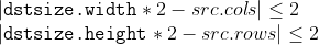
///
/// The function performs the downsampling step of the Gaussian pyramid construction. First, it
/// convolves the source image with the kernel:
///
/// 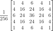
///
/// Then, it downsamples the image by rejecting even rows and columns.
///
/// ## Parameters
/// * src: input image.
/// * dst: output image; it has the specified size and the same type as src.
/// * dstsize: size of the output image.
/// * borderType: Pixel extrapolation method, see #BorderTypes (#BORDER_CONSTANT isn't supported)
///
/// ## C++ default parameters
/// * dstsize: Size()
/// * border_type: BORDER_DEFAULT
pub fn pyr_down(src: &dyn core::ToInputArray, dst: &mut dyn core::ToOutputArray, dstsize: core::Size, border_type: i32) -> Result<()> {
input_array_arg!(src);
output_array_arg!(dst);
unsafe { sys::cv_pyrDown__InputArray__OutputArray_Size_int(src.as_raw__InputArray(), dst.as_raw__OutputArray(), dstsize, border_type) }.into_result()
}
/// Performs initial step of meanshift segmentation of an image.
///
/// The function implements the filtering stage of meanshift segmentation, that is, the output of the
/// function is the filtered "posterized" image with color gradients and fine-grain texture flattened.
/// At every pixel (X,Y) of the input image (or down-sized input image, see below) the function executes
/// meanshift iterations, that is, the pixel (X,Y) neighborhood in the joint space-color hyperspace is
/// considered:
///
/// 
///
/// where (R,G,B) and (r,g,b) are the vectors of color components at (X,Y) and (x,y), respectively
/// (though, the algorithm does not depend on the color space used, so any 3-component color space can
/// be used instead). Over the neighborhood the average spatial value (X',Y') and average color vector
/// (R',G',B') are found and they act as the neighborhood center on the next iteration:
///
/// 
///
/// After the iterations over, the color components of the initial pixel (that is, the pixel from where
/// the iterations started) are set to the final value (average color at the last iteration):
///
/// 
///
/// When maxLevel \> 0, the gaussian pyramid of maxLevel+1 levels is built, and the above procedure is
/// run on the smallest layer first. After that, the results are propagated to the larger layer and the
/// iterations are run again only on those pixels where the layer colors differ by more than sr from the
/// lower-resolution layer of the pyramid. That makes boundaries of color regions sharper. Note that the
/// results will be actually different from the ones obtained by running the meanshift procedure on the
/// whole original image (i.e. when maxLevel==0).
///
/// ## Parameters
/// * src: The source 8-bit, 3-channel image.
/// * dst: The destination image of the same format and the same size as the source.
/// * sp: The spatial window radius.
/// * sr: The color window radius.
/// * maxLevel: Maximum level of the pyramid for the segmentation.
/// * termcrit: Termination criteria: when to stop meanshift iterations.
///
/// ## C++ default parameters
/// * max_level: 1
/// * termcrit: TermCriteria(TermCriteria::MAX_ITER+TermCriteria::EPS,5,1)
pub fn pyr_mean_shift_filtering(src: &dyn core::ToInputArray, dst: &mut dyn core::ToOutputArray, sp: f64, sr: f64, max_level: i32, termcrit: &core::TermCriteria) -> Result<()> {
input_array_arg!(src);
output_array_arg!(dst);
unsafe { sys::cv_pyrMeanShiftFiltering__InputArray__OutputArray_double_double_int_TermCriteria(src.as_raw__InputArray(), dst.as_raw__OutputArray(), sp, sr, max_level, termcrit.as_raw_TermCriteria()) }.into_result()
}
/// Upsamples an image and then blurs it.
///
/// By default, size of the output image is computed as `Size(src.cols\*2, (src.rows\*2)`, but in any
/// case, the following conditions should be satisfied:
///
/// 
///
/// The function performs the upsampling step of the Gaussian pyramid construction, though it can
/// actually be used to construct the Laplacian pyramid. First, it upsamples the source image by
/// injecting even zero rows and columns and then convolves the result with the same kernel as in
/// pyrDown multiplied by 4.
///
/// ## Parameters
/// * src: input image.
/// * dst: output image. It has the specified size and the same type as src .
/// * dstsize: size of the output image.
/// * borderType: Pixel extrapolation method, see #BorderTypes (only #BORDER_DEFAULT is supported)
///
/// ## C++ default parameters
/// * dstsize: Size()
/// * border_type: BORDER_DEFAULT
pub fn pyr_up(src: &dyn core::ToInputArray, dst: &mut dyn core::ToOutputArray, dstsize: core::Size, border_type: i32) -> Result<()> {
input_array_arg!(src);
output_array_arg!(dst);
unsafe { sys::cv_pyrUp__InputArray__OutputArray_Size_int(src.as_raw__InputArray(), dst.as_raw__OutputArray(), dstsize, border_type) }.into_result()
}
/// Draws a simple, thick, or filled up-right rectangle.
///
/// The function cv::rectangle draws a rectangle outline or a filled rectangle whose two opposite corners
/// are pt1 and pt2.
///
/// ## Parameters
/// * img: Image.
/// * pt1: Vertex of the rectangle.
/// * pt2: Vertex of the rectangle opposite to pt1 .
/// * color: Rectangle color or brightness (grayscale image).
/// * thickness: Thickness of lines that make up the rectangle. Negative values, like #FILLED,
/// mean that the function has to draw a filled rectangle.
/// * lineType: Type of the line. See #LineTypes
/// * shift: Number of fractional bits in the point coordinates.
///
/// ## Overloaded parameters
///
///
/// use `rec` parameter as alternative specification of the drawn rectangle: `r.tl() and
/// r.br()-Point(1,1)` are opposite corners
///
/// ## C++ default parameters
/// * thickness: 1
/// * line_type: LINE_8
/// * shift: 0
pub fn rectangle(img: &mut core::Mat, rec: core::Rect, color: core::Scalar, thickness: i32, line_type: i32, shift: i32) -> Result<()> {
unsafe { sys::cv_rectangle_Mat_Rect_Scalar_int_int_int(img.as_raw_Mat(), rec, color, thickness, line_type, shift) }.into_result()
}
/// Draws a simple, thick, or filled up-right rectangle.
///
/// The function cv::rectangle draws a rectangle outline or a filled rectangle whose two opposite corners
/// are pt1 and pt2.
///
/// ## Parameters
/// * img: Image.
/// * pt1: Vertex of the rectangle.
/// * pt2: Vertex of the rectangle opposite to pt1 .
/// * color: Rectangle color or brightness (grayscale image).
/// * thickness: Thickness of lines that make up the rectangle. Negative values, like #FILLED,
/// mean that the function has to draw a filled rectangle.
/// * lineType: Type of the line. See #LineTypes
/// * shift: Number of fractional bits in the point coordinates.
///
/// ## C++ default parameters
/// * thickness: 1
/// * line_type: LINE_8
/// * shift: 0
pub fn rectangle_points(img: &mut dyn core::ToInputOutputArray, pt1: core::Point, pt2: core::Point, color: core::Scalar, thickness: i32, line_type: i32, shift: i32) -> Result<()> {
input_output_array_arg!(img);
unsafe { sys::cv_rectangle__InputOutputArray_Point_Point_Scalar_int_int_int(img.as_raw__InputOutputArray(), pt1, pt2, color, thickness, line_type, shift) }.into_result()
}
/// Applies a generic geometrical transformation to an image.
///
/// The function remap transforms the source image using the specified map:
///
/// 
///
/// where values of pixels with non-integer coordinates are computed using one of available
/// interpolation methods.  and  can be encoded as separate floating-point maps
/// in  and  respectively, or interleaved floating-point maps of  in
/// , or fixed-point maps created by using convertMaps. The reason you might want to
/// convert from floating to fixed-point representations of a map is that they can yield much faster
/// (\~2x) remapping operations. In the converted case,  contains pairs (cvFloor(x),
/// cvFloor(y)) and  contains indices in a table of interpolation coefficients.
///
/// This function cannot operate in-place.
///
/// ## Parameters
/// * src: Source image.
/// * dst: Destination image. It has the same size as map1 and the same type as src .
/// * map1: The first map of either (x,y) points or just x values having the type CV_16SC2 ,
/// CV_32FC1, or CV_32FC2. See convertMaps for details on converting a floating point
/// representation to fixed-point for speed.
/// * map2: The second map of y values having the type CV_16UC1, CV_32FC1, or none (empty map
/// if map1 is (x,y) points), respectively.
/// * interpolation: Interpolation method (see #InterpolationFlags). The method #INTER_AREA is
/// not supported by this function.
/// * borderMode: Pixel extrapolation method (see #BorderTypes). When
/// borderMode=#BORDER_TRANSPARENT, it means that the pixels in the destination image that
/// corresponds to the "outliers" in the source image are not modified by the function.
/// * borderValue: Value used in case of a constant border. By default, it is 0.
///
/// Note:
/// Due to current implementation limitations the size of an input and output images should be less than 32767x32767.
///
/// ## C++ default parameters
/// * border_mode: BORDER_CONSTANT
/// * border_value: Scalar()
pub fn remap(src: &dyn core::ToInputArray, dst: &mut dyn core::ToOutputArray, map1: &dyn core::ToInputArray, map2: &dyn core::ToInputArray, interpolation: i32, border_mode: i32, border_value: core::Scalar) -> Result<()> {
input_array_arg!(src);
output_array_arg!(dst);
input_array_arg!(map1);
input_array_arg!(map2);
unsafe { sys::cv_remap__InputArray__OutputArray__InputArray__InputArray_int_int_Scalar(src.as_raw__InputArray(), dst.as_raw__OutputArray(), map1.as_raw__InputArray(), map2.as_raw__InputArray(), interpolation, border_mode, border_value) }.into_result()
}
/// Resizes an image.
///
/// The function resize resizes the image src down to or up to the specified size. Note that the
/// initial dst type or size are not taken into account. Instead, the size and type are derived from
/// the `src`,`dsize`,`fx`, and `fy`. If you want to resize src so that it fits the pre-created dst,
/// you may call the function as follows:
/// ```ignore
/// // explicitly specify dsize=dst.size(); fx and fy will be computed from that.
/// resize(src, dst, dst.size(), 0, 0, interpolation);
/// ```
///
/// If you want to decimate the image by factor of 2 in each direction, you can call the function this
/// way:
/// ```ignore
/// // specify fx and fy and let the function compute the destination image size.
/// resize(src, dst, Size(), 0.5, 0.5, interpolation);
/// ```
///
/// To shrink an image, it will generally look best with #INTER_AREA interpolation, whereas to
/// enlarge an image, it will generally look best with c#INTER_CUBIC (slow) or #INTER_LINEAR
/// (faster but still looks OK).
///
/// ## Parameters
/// * src: input image.
/// * dst: output image; it has the size dsize (when it is non-zero) or the size computed from
/// src.size(), fx, and fy; the type of dst is the same as of src.
/// * dsize: output image size; if it equals zero, it is computed as:
/// 
/// Either dsize or both fx and fy must be non-zero.
/// * fx: scale factor along the horizontal axis; when it equals 0, it is computed as
/// 
/// * fy: scale factor along the vertical axis; when it equals 0, it is computed as
/// 
/// * interpolation: interpolation method, see #InterpolationFlags
///
/// ## See also
/// warpAffine, warpPerspective, remap
///
/// ## C++ default parameters
/// * fx: 0
/// * fy: 0
/// * interpolation: INTER_LINEAR
pub fn resize(src: &dyn core::ToInputArray, dst: &mut dyn core::ToOutputArray, dsize: core::Size, fx: f64, fy: f64, interpolation: i32) -> Result<()> {
input_array_arg!(src);
output_array_arg!(dst);
unsafe { sys::cv_resize__InputArray__OutputArray_Size_double_double_int(src.as_raw__InputArray(), dst.as_raw__OutputArray(), dsize, fx, fy, interpolation) }.into_result()
}
/// Finds out if there is any intersection between two rotated rectangles.
///
/// If there is then the vertices of the intersecting region are returned as well.
///
/// Below are some examples of intersection configurations. The hatched pattern indicates the
/// intersecting region and the red vertices are returned by the function.
///
/// 
///
/// ## Parameters
/// * rect1: First rectangle
/// * rect2: Second rectangle
/// * intersectingRegion: The output array of the vertices of the intersecting region. It returns
/// at most 8 vertices. Stored as std::vector\<cv::Point2f\> or cv::Mat as Mx1 of type CV_32FC2.
/// ## Returns
/// One of #RectanglesIntersectTypes
pub fn rotated_rectangle_intersection(rect1: &core::RotatedRect, rect2: &core::RotatedRect, intersecting_region: &mut dyn core::ToOutputArray) -> Result<i32> {
output_array_arg!(intersecting_region);
unsafe { sys::cv_rotatedRectangleIntersection_RotatedRect_RotatedRect__OutputArray(rect1.as_raw_RotatedRect(), rect2.as_raw_RotatedRect(), intersecting_region.as_raw__OutputArray()) }.into_result()
}
/// Applies a separable linear filter to an image.
///
/// The function applies a separable linear filter to the image. That is, first, every row of src is
/// filtered with the 1D kernel kernelX. Then, every column of the result is filtered with the 1D
/// kernel kernelY. The final result shifted by delta is stored in dst .
///
/// ## Parameters
/// * src: Source image.
/// * dst: Destination image of the same size and the same number of channels as src .
/// * ddepth: Destination image depth, see @ref filter_depths "combinations"
/// * kernelX: Coefficients for filtering each row.
/// * kernelY: Coefficients for filtering each column.
/// * anchor: Anchor position within the kernel. The default value  means that the anchor
/// is at the kernel center.
/// * delta: Value added to the filtered results before storing them.
/// * borderType: Pixel extrapolation method, see #BorderTypes
/// ## See also
/// filter2D, Sobel, GaussianBlur, boxFilter, blur
///
/// ## C++ default parameters
/// * anchor: Point(-1,-1)
/// * delta: 0
/// * border_type: BORDER_DEFAULT
pub fn sep_filter_2d(src: &dyn core::ToInputArray, dst: &mut dyn core::ToOutputArray, ddepth: i32, kernel_x: &dyn core::ToInputArray, kernel_y: &dyn core::ToInputArray, anchor: core::Point, delta: f64, border_type: i32) -> Result<()> {
input_array_arg!(src);
output_array_arg!(dst);
input_array_arg!(kernel_x);
input_array_arg!(kernel_y);
unsafe { sys::cv_sepFilter2D__InputArray__OutputArray_int__InputArray__InputArray_Point_double_int(src.as_raw__InputArray(), dst.as_raw__OutputArray(), ddepth, kernel_x.as_raw__InputArray(), kernel_y.as_raw__InputArray(), anchor, delta, border_type) }.into_result()
}
/// Calculates the first order image derivative in both x and y using a Sobel operator
///
/// Equivalent to calling:
///
/// ```ignore
/// Sobel( src, dx, CV_16SC1, 1, 0, 3 );
/// Sobel( src, dy, CV_16SC1, 0, 1, 3 );
/// ```
///
///
/// ## Parameters
/// * src: input image.
/// * dx: output image with first-order derivative in x.
/// * dy: output image with first-order derivative in y.
/// * ksize: size of Sobel kernel. It must be 3.
/// * borderType: pixel extrapolation method, see #BorderTypes
///
/// ## See also
/// Sobel
///
/// ## C++ default parameters
/// * ksize: 3
/// * border_type: BORDER_DEFAULT
pub fn spatial_gradient(src: &dyn core::ToInputArray, dx: &mut dyn core::ToOutputArray, dy: &mut dyn core::ToOutputArray, ksize: i32, border_type: i32) -> Result<()> {
input_array_arg!(src);
output_array_arg!(dx);
output_array_arg!(dy);
unsafe { sys::cv_spatialGradient__InputArray__OutputArray__OutputArray_int_int(src.as_raw__InputArray(), dx.as_raw__OutputArray(), dy.as_raw__OutputArray(), ksize, border_type) }.into_result()
}
/// Calculates the normalized sum of squares of the pixel values overlapping the filter.
///
/// For every pixel  in the source image, the function calculates the sum of squares of those neighboring
/// pixel values which overlap the filter placed over the pixel .
///
/// The unnormalized square box filter can be useful in computing local image statistics such as the the local
/// variance and standard deviation around the neighborhood of a pixel.
///
/// ## Parameters
/// * src: input image
/// * dst: output image of the same size and type as _src
/// * ddepth: the output image depth (-1 to use src.depth())
/// * ksize: kernel size
/// * anchor: kernel anchor point. The default value of Point(-1, -1) denotes that the anchor is at the kernel
/// center.
/// * normalize: flag, specifying whether the kernel is to be normalized by it's area or not.
/// * borderType: border mode used to extrapolate pixels outside of the image, see #BorderTypes
/// ## See also
/// boxFilter
///
/// ## C++ default parameters
/// * anchor: Point(-1, -1)
/// * normalize: true
/// * border_type: BORDER_DEFAULT
pub fn sqr_box_filter(src: &dyn core::ToInputArray, dst: &mut dyn core::ToOutputArray, ddepth: i32, ksize: core::Size, anchor: core::Point, normalize: bool, border_type: i32) -> Result<()> {
input_array_arg!(src);
output_array_arg!(dst);
unsafe { sys::cv_sqrBoxFilter__InputArray__OutputArray_int_Size_Point_bool_int(src.as_raw__InputArray(), dst.as_raw__OutputArray(), ddepth, ksize, anchor, normalize, border_type) }.into_result()
}
/// Applies a fixed-level threshold to each array element.
///
/// The function applies fixed-level thresholding to a multiple-channel array. The function is typically
/// used to get a bi-level (binary) image out of a grayscale image ( #compare could be also used for
/// this purpose) or for removing a noise, that is, filtering out pixels with too small or too large
/// values. There are several types of thresholding supported by the function. They are determined by
/// type parameter.
///
/// Also, the special values #THRESH_OTSU or #THRESH_TRIANGLE may be combined with one of the
/// above values. In these cases, the function determines the optimal threshold value using the Otsu's
/// or Triangle algorithm and uses it instead of the specified thresh.
///
///
/// Note: Currently, the Otsu's and Triangle methods are implemented only for 8-bit single-channel images.
///
/// ## Parameters
/// * src: input array (multiple-channel, 8-bit or 32-bit floating point).
/// * dst: output array of the same size and type and the same number of channels as src.
/// * thresh: threshold value.
/// * maxval: maximum value to use with the #THRESH_BINARY and #THRESH_BINARY_INV thresholding
/// types.
/// * type: thresholding type (see #ThresholdTypes).
/// ## Returns
/// the computed threshold value if Otsu's or Triangle methods used.
///
/// ## See also
/// adaptiveThreshold, findContours, compare, min, max
pub fn threshold(src: &dyn core::ToInputArray, dst: &mut dyn core::ToOutputArray, thresh: f64, maxval: f64, _type: i32) -> Result<f64> {
input_array_arg!(src);
output_array_arg!(dst);
unsafe { sys::cv_threshold__InputArray__OutputArray_double_double_int(src.as_raw__InputArray(), dst.as_raw__OutputArray(), thresh, maxval, _type) }.into_result()
}
/// Computes the ideal point coordinates from the observed point coordinates.
///
/// The function is similar to #undistort and #initUndistortRectifyMap but it operates on a
/// sparse set of points instead of a raster image. Also the function performs a reverse transformation
/// to projectPoints. In case of a 3D object, it does not reconstruct its 3D coordinates, but for a
/// planar object, it does, up to a translation vector, if the proper R is specified.
///
/// For each observed point coordinate  the function computes:
/// 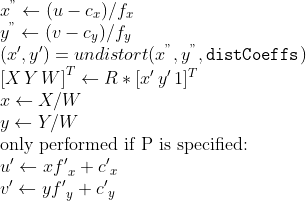
///
/// where *undistort* is an approximate iterative algorithm that estimates the normalized original
/// point coordinates out of the normalized distorted point coordinates ("normalized" means that the
/// coordinates do not depend on the camera matrix).
///
/// The function can be used for both a stereo camera head or a monocular camera (when R is empty).
/// ## Parameters
/// * src: Observed point coordinates, 2xN/Nx2 1-channel or 1xN/Nx1 2-channel (CV_32FC2 or CV_64FC2) (or
/// vector\<Point2f\> ).
/// * dst: Output ideal point coordinates (1xN/Nx1 2-channel or vector\<Point2f\> ) after undistortion and reverse perspective
/// transformation. If matrix P is identity or omitted, dst will contain normalized point coordinates.
/// * cameraMatrix: Camera matrix  .
/// * distCoeffs: Input vector of distortion coefficients
/// 
/// of 4, 5, 8, 12 or 14 elements. If the vector is NULL/empty, the zero distortion coefficients are assumed.
/// * R: Rectification transformation in the object space (3x3 matrix). R1 or R2 computed by
/// #stereoRectify can be passed here. If the matrix is empty, the identity transformation is used.
/// * P: New camera matrix (3x3) or new projection matrix (3x4) 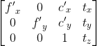. P1 or P2 computed by
/// #stereoRectify can be passed here. If the matrix is empty, the identity new camera matrix is used.
///
/// ## C++ default parameters
/// * r: noArray()
/// * p: noArray()
pub fn undistort_points(src: &dyn core::ToInputArray, dst: &mut dyn core::ToOutputArray, camera_matrix: &dyn core::ToInputArray, dist_coeffs: &dyn core::ToInputArray, r: &dyn core::ToInputArray, p: &dyn core::ToInputArray) -> Result<()> {
input_array_arg!(src);
output_array_arg!(dst);
input_array_arg!(camera_matrix);
input_array_arg!(dist_coeffs);
input_array_arg!(r);
input_array_arg!(p);
unsafe { sys::cv_undistortPoints__InputArray__OutputArray__InputArray__InputArray__InputArray__InputArray(src.as_raw__InputArray(), dst.as_raw__OutputArray(), camera_matrix.as_raw__InputArray(), dist_coeffs.as_raw__InputArray(), r.as_raw__InputArray(), p.as_raw__InputArray()) }.into_result()
}
/// Computes the ideal point coordinates from the observed point coordinates.
///
/// The function is similar to #undistort and #initUndistortRectifyMap but it operates on a
/// sparse set of points instead of a raster image. Also the function performs a reverse transformation
/// to projectPoints. In case of a 3D object, it does not reconstruct its 3D coordinates, but for a
/// planar object, it does, up to a translation vector, if the proper R is specified.
///
/// For each observed point coordinate  the function computes:
/// 
///
/// where *undistort* is an approximate iterative algorithm that estimates the normalized original
/// point coordinates out of the normalized distorted point coordinates ("normalized" means that the
/// coordinates do not depend on the camera matrix).
///
/// The function can be used for both a stereo camera head or a monocular camera (when R is empty).
/// ## Parameters
/// * src: Observed point coordinates, 2xN/Nx2 1-channel or 1xN/Nx1 2-channel (CV_32FC2 or CV_64FC2) (or
/// vector\<Point2f\> ).
/// * dst: Output ideal point coordinates (1xN/Nx1 2-channel or vector\<Point2f\> ) after undistortion and reverse perspective
/// transformation. If matrix P is identity or omitted, dst will contain normalized point coordinates.
/// * cameraMatrix: Camera matrix  .
/// * distCoeffs: Input vector of distortion coefficients
/// 
/// of 4, 5, 8, 12 or 14 elements. If the vector is NULL/empty, the zero distortion coefficients are assumed.
/// * R: Rectification transformation in the object space (3x3 matrix). R1 or R2 computed by
/// #stereoRectify can be passed here. If the matrix is empty, the identity transformation is used.
/// * P: New camera matrix (3x3) or new projection matrix (3x4) . P1 or P2 computed by
/// #stereoRectify can be passed here. If the matrix is empty, the identity new camera matrix is used.
///
/// ## Overloaded parameters
///
///
/// Note: Default version of #undistortPoints does 5 iterations to compute undistorted points.
pub fn undistort_points_with_criteria(src: &dyn core::ToInputArray, dst: &mut dyn core::ToOutputArray, camera_matrix: &dyn core::ToInputArray, dist_coeffs: &dyn core::ToInputArray, r: &dyn core::ToInputArray, p: &dyn core::ToInputArray, criteria: &core::TermCriteria) -> Result<()> {
input_array_arg!(src);
output_array_arg!(dst);
input_array_arg!(camera_matrix);
input_array_arg!(dist_coeffs);
input_array_arg!(r);
input_array_arg!(p);
unsafe { sys::cv_undistortPoints__InputArray__OutputArray__InputArray__InputArray__InputArray__InputArray_TermCriteria(src.as_raw__InputArray(), dst.as_raw__OutputArray(), camera_matrix.as_raw__InputArray(), dist_coeffs.as_raw__InputArray(), r.as_raw__InputArray(), p.as_raw__InputArray(), criteria.as_raw_TermCriteria()) }.into_result()
}
/// Transforms an image to compensate for lens distortion.
///
/// The function transforms an image to compensate radial and tangential lens distortion.
///
/// The function is simply a combination of #initUndistortRectifyMap (with unity R ) and #remap
/// (with bilinear interpolation). See the former function for details of the transformation being
/// performed.
///
/// Those pixels in the destination image, for which there is no correspondent pixels in the source
/// image, are filled with zeros (black color).
///
/// A particular subset of the source image that will be visible in the corrected image can be regulated
/// by newCameraMatrix. You can use #getOptimalNewCameraMatrix to compute the appropriate
/// newCameraMatrix depending on your requirements.
///
/// The camera matrix and the distortion parameters can be determined using #calibrateCamera. If
/// the resolution of images is different from the resolution used at the calibration stage,  and  need to be scaled accordingly, while the distortion coefficients remain
/// the same.
///
/// ## Parameters
/// * src: Input (distorted) image.
/// * dst: Output (corrected) image that has the same size and type as src .
/// * cameraMatrix: Input camera matrix 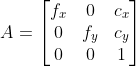 .
/// * distCoeffs: Input vector of distortion coefficients
/// 
/// of 4, 5, 8, 12 or 14 elements. If the vector is NULL/empty, the zero distortion coefficients are assumed.
/// * newCameraMatrix: Camera matrix of the distorted image. By default, it is the same as
/// cameraMatrix but you may additionally scale and shift the result by using a different matrix.
///
/// ## C++ default parameters
/// * new_camera_matrix: noArray()
pub fn undistort(src: &dyn core::ToInputArray, dst: &mut dyn core::ToOutputArray, camera_matrix: &dyn core::ToInputArray, dist_coeffs: &dyn core::ToInputArray, new_camera_matrix: &dyn core::ToInputArray) -> Result<()> {
input_array_arg!(src);
output_array_arg!(dst);
input_array_arg!(camera_matrix);
input_array_arg!(dist_coeffs);
input_array_arg!(new_camera_matrix);
unsafe { sys::cv_undistort__InputArray__OutputArray__InputArray__InputArray__InputArray(src.as_raw__InputArray(), dst.as_raw__OutputArray(), camera_matrix.as_raw__InputArray(), dist_coeffs.as_raw__InputArray(), new_camera_matrix.as_raw__InputArray()) }.into_result()
}
/// Applies an affine transformation to an image.
///
/// The function warpAffine transforms the source image using the specified matrix:
///
/// 
///
/// when the flag #WARP_INVERSE_MAP is set. Otherwise, the transformation is first inverted
/// with #invertAffineTransform and then put in the formula above instead of M. The function cannot
/// operate in-place.
///
/// ## Parameters
/// * src: input image.
/// * dst: output image that has the size dsize and the same type as src .
/// * M:  transformation matrix.
/// * dsize: size of the output image.
/// * flags: combination of interpolation methods (see #InterpolationFlags) and the optional
/// flag #WARP_INVERSE_MAP that means that M is the inverse transformation (
///  ).
/// * borderMode: pixel extrapolation method (see #BorderTypes); when
/// borderMode=#BORDER_TRANSPARENT, it means that the pixels in the destination image corresponding to
/// the "outliers" in the source image are not modified by the function.
/// * borderValue: value used in case of a constant border; by default, it is 0.
///
/// ## See also
/// warpPerspective, resize, remap, getRectSubPix, transform
///
/// ## C++ default parameters
/// * flags: INTER_LINEAR
/// * border_mode: BORDER_CONSTANT
/// * border_value: Scalar()
pub fn warp_affine(src: &dyn core::ToInputArray, dst: &mut dyn core::ToOutputArray, m: &dyn core::ToInputArray, dsize: core::Size, flags: i32, border_mode: i32, border_value: core::Scalar) -> Result<()> {
input_array_arg!(src);
output_array_arg!(dst);
input_array_arg!(m);
unsafe { sys::cv_warpAffine__InputArray__OutputArray__InputArray_Size_int_int_Scalar(src.as_raw__InputArray(), dst.as_raw__OutputArray(), m.as_raw__InputArray(), dsize, flags, border_mode, border_value) }.into_result()
}
/// Applies a perspective transformation to an image.
///
/// The function warpPerspective transforms the source image using the specified matrix:
///
/// 
///
/// when the flag #WARP_INVERSE_MAP is set. Otherwise, the transformation is first inverted with invert
/// and then put in the formula above instead of M. The function cannot operate in-place.
///
/// ## Parameters
/// * src: input image.
/// * dst: output image that has the size dsize and the same type as src .
/// * M:  transformation matrix.
/// * dsize: size of the output image.
/// * flags: combination of interpolation methods (#INTER_LINEAR or #INTER_NEAREST) and the
/// optional flag #WARP_INVERSE_MAP, that sets M as the inverse transformation (
///  ).
/// * borderMode: pixel extrapolation method (#BORDER_CONSTANT or #BORDER_REPLICATE).
/// * borderValue: value used in case of a constant border; by default, it equals 0.
///
/// ## See also
/// warpAffine, resize, remap, getRectSubPix, perspectiveTransform
///
/// ## C++ default parameters
/// * flags: INTER_LINEAR
/// * border_mode: BORDER_CONSTANT
/// * border_value: Scalar()
pub fn warp_perspective(src: &dyn core::ToInputArray, dst: &mut dyn core::ToOutputArray, m: &dyn core::ToInputArray, dsize: core::Size, flags: i32, border_mode: i32, border_value: core::Scalar) -> Result<()> {
input_array_arg!(src);
output_array_arg!(dst);
input_array_arg!(m);
unsafe { sys::cv_warpPerspective__InputArray__OutputArray__InputArray_Size_int_int_Scalar(src.as_raw__InputArray(), dst.as_raw__OutputArray(), m.as_raw__InputArray(), dsize, flags, border_mode, border_value) }.into_result()
}
/// \brief Remaps an image to polar or semilog-polar coordinates space
///
/// @anchor polar_remaps_reference_image
/// 
///
/// Transform the source image using the following transformation:
/// 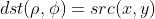
///
/// where
/// 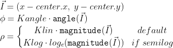
///
/// and
/// 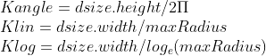
///
///
/// \par Linear vs semilog mapping
///
/// Polar mapping can be linear or semi-log. Add one of #WarpPolarMode to `flags` to specify the polar mapping mode.
///
/// Linear is the default mode.
///
/// The semilog mapping emulates the human "foveal" vision that permit very high acuity on the line of sight (central vision)
/// in contrast to peripheral vision where acuity is minor.
///
/// \par Option on `dsize`:
///
/// - if both values in `dsize <=0 ` (default),
/// the destination image will have (almost) same area of source bounding circle:
/// 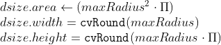
///
///
/// - if only `dsize.height <= 0`,
/// the destination image area will be proportional to the bounding circle area but scaled by `Kx * Kx`:
/// 
///
/// - if both values in `dsize > 0 `,
/// the destination image will have the given size therefore the area of the bounding circle will be scaled to `dsize`.
///
///
/// \par Reverse mapping
///
/// You can get reverse mapping adding #WARP_INVERSE_MAP to `flags`
/// \snippet polar_transforms.cpp InverseMap
///
/// In addiction, to calculate the original coordinate from a polar mapped coordinate :
/// \snippet polar_transforms.cpp InverseCoordinate
///
/// ## Parameters
/// * src: Source image.
/// * dst: Destination image. It will have same type as src.
/// * dsize: The destination image size (see description for valid options).
/// * center: The transformation center.
/// * maxRadius: The radius of the bounding circle to transform. It determines the inverse magnitude scale parameter too.
/// * flags: A combination of interpolation methods, #InterpolationFlags + #WarpPolarMode.
/// - Add #WARP_POLAR_LINEAR to select linear polar mapping (default)
/// - Add #WARP_POLAR_LOG to select semilog polar mapping
/// - Add #WARP_INVERSE_MAP for reverse mapping.
///
/// Note:
/// * The function can not operate in-place.
/// * To calculate magnitude and angle in degrees #cartToPolar is used internally thus angles are measured from 0 to 360 with accuracy about 0.3 degrees.
/// * This function uses #remap. Due to current implementation limitations the size of an input and output images should be less than 32767x32767.
///
/// ## See also
/// cv::remap
pub fn warp_polar(src: &dyn core::ToInputArray, dst: &mut dyn core::ToOutputArray, dsize: core::Size, center: core::Point2f, max_radius: f64, flags: i32) -> Result<()> {
input_array_arg!(src);
output_array_arg!(dst);
unsafe { sys::cv_warpPolar__InputArray__OutputArray_Size_Point2f_double_int(src.as_raw__InputArray(), dst.as_raw__OutputArray(), dsize, center, max_radius, flags) }.into_result()
}
/// Performs a marker-based image segmentation using the watershed algorithm.
///
/// The function implements one of the variants of watershed, non-parametric marker-based segmentation
/// algorithm, described in [Meyer92](https://docs.opencv.org/3.4.7/d0/de3/citelist.html#CITEREF_Meyer92) .
///
/// Before passing the image to the function, you have to roughly outline the desired regions in the
/// image markers with positive (\>0) indices. So, every region is represented as one or more connected
/// components with the pixel values 1, 2, 3, and so on. Such markers can be retrieved from a binary
/// mask using #findContours and #drawContours (see the watershed.cpp demo). The markers are "seeds" of
/// the future image regions. All the other pixels in markers , whose relation to the outlined regions
/// is not known and should be defined by the algorithm, should be set to 0's. In the function output,
/// each pixel in markers is set to a value of the "seed" components or to -1 at boundaries between the
/// regions.
///
///
/// Note: Any two neighbor connected components are not necessarily separated by a watershed boundary
/// (-1's pixels); for example, they can touch each other in the initial marker image passed to the
/// function.
///
/// ## Parameters
/// * image: Input 8-bit 3-channel image.
/// * markers: Input/output 32-bit single-channel image (map) of markers. It should have the same
/// size as image .
///
/// ## See also
/// findContours
///
/// @ingroup imgproc_misc
pub fn watershed(image: &dyn core::ToInputArray, markers: &mut dyn core::ToInputOutputArray) -> Result<()> {
input_array_arg!(image);
input_output_array_arg!(markers);
unsafe { sys::cv_watershed__InputArray__InputOutputArray(image.as_raw__InputArray(), markers.as_raw__InputOutputArray()) }.into_result()
}
///
/// ## C++ default parameters
/// * cost: noArray()
/// * lower_bound: Ptr<float>()
/// * flow: noArray()
pub fn wrapper_emd(signature1: &dyn core::ToInputArray, signature2: &dyn core::ToInputArray, dist_type: i32, cost: &dyn core::ToInputArray, lower_bound: &types::PtrOffloat, flow: &mut dyn core::ToOutputArray) -> Result<f32> {
input_array_arg!(signature1);
input_array_arg!(signature2);
input_array_arg!(cost);
output_array_arg!(flow);
unsafe { sys::cv_wrapperEMD__InputArray__InputArray_int__InputArray_PtrOffloat__OutputArray(signature1.as_raw__InputArray(), signature2.as_raw__InputArray(), dist_type, cost.as_raw__InputArray(), lower_bound.as_raw_PtrOffloat(), flow.as_raw__OutputArray()) }.into_result()
}
// Generating impl for trait cv::CLAHE (trait)
/// Base class for Contrast Limited Adaptive Histogram Equalization.
pub trait CLAHE: core::Algorithm {
#[inline(always)] fn as_raw_CLAHE(&self) -> *mut c_void;
/// Equalizes the histogram of a grayscale image using Contrast Limited Adaptive Histogram Equalization.
///
/// ## Parameters
/// * src: Source image of type CV_8UC1 or CV_16UC1.
/// * dst: Destination image.
fn apply(&mut self, src: &dyn core::ToInputArray, dst: &mut dyn core::ToOutputArray) -> Result<()> {
input_array_arg!(src);
output_array_arg!(dst);
unsafe { sys::cv_CLAHE_apply__InputArray__OutputArray(self.as_raw_CLAHE(), src.as_raw__InputArray(), dst.as_raw__OutputArray()) }.into_result()
}
/// Sets threshold for contrast limiting.
///
/// ## Parameters
/// * clipLimit: threshold value.
fn set_clip_limit(&mut self, clip_limit: f64) -> Result<()> {
unsafe { sys::cv_CLAHE_setClipLimit_double(self.as_raw_CLAHE(), clip_limit) }.into_result()
}
/// Returns threshold value for contrast limiting.
fn get_clip_limit(&self) -> Result<f64> {
unsafe { sys::cv_CLAHE_getClipLimit_const(self.as_raw_CLAHE()) }.into_result()
}
/// Sets size of grid for histogram equalization. Input image will be divided into
/// equally sized rectangular tiles.
///
/// ## Parameters
/// * tileGridSize: defines the number of tiles in row and column.
fn set_tiles_grid_size(&mut self, tile_grid_size: core::Size) -> Result<()> {
unsafe { sys::cv_CLAHE_setTilesGridSize_Size(self.as_raw_CLAHE(), tile_grid_size) }.into_result()
}
/// Returns Size defines the number of tiles in row and column.
fn get_tiles_grid_size(&self) -> Result<core::Size> {
unsafe { sys::cv_CLAHE_getTilesGridSize_const(self.as_raw_CLAHE()) }.into_result()
}
fn collect_garbage(&mut self) -> Result<()> {
unsafe { sys::cv_CLAHE_collectGarbage(self.as_raw_CLAHE()) }.into_result()
}
}
// Generating impl for trait cv::GeneralizedHough (trait)
/// finds arbitrary template in the grayscale image using Generalized Hough Transform
pub trait GeneralizedHough: core::Algorithm {
#[inline(always)] fn as_raw_GeneralizedHough(&self) -> *mut c_void;
/// set template to search
///
/// ## C++ default parameters
/// * templ_center: Point(-1, -1)
fn set_template(&mut self, templ: &dyn core::ToInputArray, templ_center: core::Point) -> Result<()> {
input_array_arg!(templ);
unsafe { sys::cv_GeneralizedHough_setTemplate__InputArray_Point(self.as_raw_GeneralizedHough(), templ.as_raw__InputArray(), templ_center) }.into_result()
}
///
/// ## C++ default parameters
/// * templ_center: Point(-1, -1)
fn set_template_1(&mut self, edges: &dyn core::ToInputArray, dx: &dyn core::ToInputArray, dy: &dyn core::ToInputArray, templ_center: core::Point) -> Result<()> {
input_array_arg!(edges);
input_array_arg!(dx);
input_array_arg!(dy);
unsafe { sys::cv_GeneralizedHough_setTemplate__InputArray__InputArray__InputArray_Point(self.as_raw_GeneralizedHough(), edges.as_raw__InputArray(), dx.as_raw__InputArray(), dy.as_raw__InputArray(), templ_center) }.into_result()
}
/// find template on image
///
/// ## C++ default parameters
/// * votes: noArray()
fn detect(&mut self, image: &dyn core::ToInputArray, positions: &mut dyn core::ToOutputArray, votes: &mut dyn core::ToOutputArray) -> Result<()> {
input_array_arg!(image);
output_array_arg!(positions);
output_array_arg!(votes);
unsafe { sys::cv_GeneralizedHough_detect__InputArray__OutputArray__OutputArray(self.as_raw_GeneralizedHough(), image.as_raw__InputArray(), positions.as_raw__OutputArray(), votes.as_raw__OutputArray()) }.into_result()
}
///
/// ## C++ default parameters
/// * votes: noArray()
fn detect_with_edges(&mut self, edges: &dyn core::ToInputArray, dx: &dyn core::ToInputArray, dy: &dyn core::ToInputArray, positions: &mut dyn core::ToOutputArray, votes: &mut dyn core::ToOutputArray) -> Result<()> {
input_array_arg!(edges);
input_array_arg!(dx);
input_array_arg!(dy);
output_array_arg!(positions);
output_array_arg!(votes);
unsafe { sys::cv_GeneralizedHough_detect__InputArray__InputArray__InputArray__OutputArray__OutputArray(self.as_raw_GeneralizedHough(), edges.as_raw__InputArray(), dx.as_raw__InputArray(), dy.as_raw__InputArray(), positions.as_raw__OutputArray(), votes.as_raw__OutputArray()) }.into_result()
}
/// Canny low threshold.
fn set_canny_low_thresh(&mut self, canny_low_thresh: i32) -> Result<()> {
unsafe { sys::cv_GeneralizedHough_setCannyLowThresh_int(self.as_raw_GeneralizedHough(), canny_low_thresh) }.into_result()
}
fn get_canny_low_thresh(&self) -> Result<i32> {
unsafe { sys::cv_GeneralizedHough_getCannyLowThresh_const(self.as_raw_GeneralizedHough()) }.into_result()
}
/// Canny high threshold.
fn set_canny_high_thresh(&mut self, canny_high_thresh: i32) -> Result<()> {
unsafe { sys::cv_GeneralizedHough_setCannyHighThresh_int(self.as_raw_GeneralizedHough(), canny_high_thresh) }.into_result()
}
fn get_canny_high_thresh(&self) -> Result<i32> {
unsafe { sys::cv_GeneralizedHough_getCannyHighThresh_const(self.as_raw_GeneralizedHough()) }.into_result()
}
/// Minimum distance between the centers of the detected objects.
fn set_min_dist(&mut self, min_dist: f64) -> Result<()> {
unsafe { sys::cv_GeneralizedHough_setMinDist_double(self.as_raw_GeneralizedHough(), min_dist) }.into_result()
}
fn get_min_dist(&self) -> Result<f64> {
unsafe { sys::cv_GeneralizedHough_getMinDist_const(self.as_raw_GeneralizedHough()) }.into_result()
}
/// Inverse ratio of the accumulator resolution to the image resolution.
fn set_dp(&mut self, dp: f64) -> Result<()> {
unsafe { sys::cv_GeneralizedHough_setDp_double(self.as_raw_GeneralizedHough(), dp) }.into_result()
}
fn get_dp(&self) -> Result<f64> {
unsafe { sys::cv_GeneralizedHough_getDp_const(self.as_raw_GeneralizedHough()) }.into_result()
}
/// Maximal size of inner buffers.
fn set_max_buffer_size(&mut self, max_buffer_size: i32) -> Result<()> {
unsafe { sys::cv_GeneralizedHough_setMaxBufferSize_int(self.as_raw_GeneralizedHough(), max_buffer_size) }.into_result()
}
fn get_max_buffer_size(&self) -> Result<i32> {
unsafe { sys::cv_GeneralizedHough_getMaxBufferSize_const(self.as_raw_GeneralizedHough()) }.into_result()
}
}
// Generating impl for trait cv::GeneralizedHoughBallard (trait)
/// finds arbitrary template in the grayscale image using Generalized Hough Transform
///
/// Detects position only without translation and rotation [Ballard1981](https://docs.opencv.org/3.4.7/d0/de3/citelist.html#CITEREF_Ballard1981) .
pub trait GeneralizedHoughBallard: crate::imgproc::GeneralizedHough {
#[inline(always)] fn as_raw_GeneralizedHoughBallard(&self) -> *mut c_void;
/// R-Table levels.
fn set_levels(&mut self, levels: i32) -> Result<()> {
unsafe { sys::cv_GeneralizedHoughBallard_setLevels_int(self.as_raw_GeneralizedHoughBallard(), levels) }.into_result()
}
fn get_levels(&self) -> Result<i32> {
unsafe { sys::cv_GeneralizedHoughBallard_getLevels_const(self.as_raw_GeneralizedHoughBallard()) }.into_result()
}
/// The accumulator threshold for the template centers at the detection stage. The smaller it is, the more false positions may be detected.
fn set_votes_threshold(&mut self, votes_threshold: i32) -> Result<()> {
unsafe { sys::cv_GeneralizedHoughBallard_setVotesThreshold_int(self.as_raw_GeneralizedHoughBallard(), votes_threshold) }.into_result()
}
fn get_votes_threshold(&self) -> Result<i32> {
unsafe { sys::cv_GeneralizedHoughBallard_getVotesThreshold_const(self.as_raw_GeneralizedHoughBallard()) }.into_result()
}
}
// Generating impl for trait cv::GeneralizedHoughGuil (trait)
/// finds arbitrary template in the grayscale image using Generalized Hough Transform
///
/// Detects position, translation and rotation [Guil1999](https://docs.opencv.org/3.4.7/d0/de3/citelist.html#CITEREF_Guil1999) .
pub trait GeneralizedHoughGuil: crate::imgproc::GeneralizedHough {
#[inline(always)] fn as_raw_GeneralizedHoughGuil(&self) -> *mut c_void;
/// Angle difference in degrees between two points in feature.
fn set_xi(&mut self, xi: f64) -> Result<()> {
unsafe { sys::cv_GeneralizedHoughGuil_setXi_double(self.as_raw_GeneralizedHoughGuil(), xi) }.into_result()
}
fn get_xi(&self) -> Result<f64> {
unsafe { sys::cv_GeneralizedHoughGuil_getXi_const(self.as_raw_GeneralizedHoughGuil()) }.into_result()
}
/// Feature table levels.
fn set_levels(&mut self, levels: i32) -> Result<()> {
unsafe { sys::cv_GeneralizedHoughGuil_setLevels_int(self.as_raw_GeneralizedHoughGuil(), levels) }.into_result()
}
fn get_levels(&self) -> Result<i32> {
unsafe { sys::cv_GeneralizedHoughGuil_getLevels_const(self.as_raw_GeneralizedHoughGuil()) }.into_result()
}
/// Maximal difference between angles that treated as equal.
fn set_angle_epsilon(&mut self, angle_epsilon: f64) -> Result<()> {
unsafe { sys::cv_GeneralizedHoughGuil_setAngleEpsilon_double(self.as_raw_GeneralizedHoughGuil(), angle_epsilon) }.into_result()
}
fn get_angle_epsilon(&self) -> Result<f64> {
unsafe { sys::cv_GeneralizedHoughGuil_getAngleEpsilon_const(self.as_raw_GeneralizedHoughGuil()) }.into_result()
}
/// Minimal rotation angle to detect in degrees.
fn set_min_angle(&mut self, min_angle: f64) -> Result<()> {
unsafe { sys::cv_GeneralizedHoughGuil_setMinAngle_double(self.as_raw_GeneralizedHoughGuil(), min_angle) }.into_result()
}
fn get_min_angle(&self) -> Result<f64> {
unsafe { sys::cv_GeneralizedHoughGuil_getMinAngle_const(self.as_raw_GeneralizedHoughGuil()) }.into_result()
}
/// Maximal rotation angle to detect in degrees.
fn set_max_angle(&mut self, max_angle: f64) -> Result<()> {
unsafe { sys::cv_GeneralizedHoughGuil_setMaxAngle_double(self.as_raw_GeneralizedHoughGuil(), max_angle) }.into_result()
}
fn get_max_angle(&self) -> Result<f64> {
unsafe { sys::cv_GeneralizedHoughGuil_getMaxAngle_const(self.as_raw_GeneralizedHoughGuil()) }.into_result()
}
/// Angle step in degrees.
fn set_angle_step(&mut self, angle_step: f64) -> Result<()> {
unsafe { sys::cv_GeneralizedHoughGuil_setAngleStep_double(self.as_raw_GeneralizedHoughGuil(), angle_step) }.into_result()
}
fn get_angle_step(&self) -> Result<f64> {
unsafe { sys::cv_GeneralizedHoughGuil_getAngleStep_const(self.as_raw_GeneralizedHoughGuil()) }.into_result()
}
/// Angle votes threshold.
fn set_angle_thresh(&mut self, angle_thresh: i32) -> Result<()> {
unsafe { sys::cv_GeneralizedHoughGuil_setAngleThresh_int(self.as_raw_GeneralizedHoughGuil(), angle_thresh) }.into_result()
}
fn get_angle_thresh(&self) -> Result<i32> {
unsafe { sys::cv_GeneralizedHoughGuil_getAngleThresh_const(self.as_raw_GeneralizedHoughGuil()) }.into_result()
}
/// Minimal scale to detect.
fn set_min_scale(&mut self, min_scale: f64) -> Result<()> {
unsafe { sys::cv_GeneralizedHoughGuil_setMinScale_double(self.as_raw_GeneralizedHoughGuil(), min_scale) }.into_result()
}
fn get_min_scale(&self) -> Result<f64> {
unsafe { sys::cv_GeneralizedHoughGuil_getMinScale_const(self.as_raw_GeneralizedHoughGuil()) }.into_result()
}
/// Maximal scale to detect.
fn set_max_scale(&mut self, max_scale: f64) -> Result<()> {
unsafe { sys::cv_GeneralizedHoughGuil_setMaxScale_double(self.as_raw_GeneralizedHoughGuil(), max_scale) }.into_result()
}
fn get_max_scale(&self) -> Result<f64> {
unsafe { sys::cv_GeneralizedHoughGuil_getMaxScale_const(self.as_raw_GeneralizedHoughGuil()) }.into_result()
}
/// Scale step.
fn set_scale_step(&mut self, scale_step: f64) -> Result<()> {
unsafe { sys::cv_GeneralizedHoughGuil_setScaleStep_double(self.as_raw_GeneralizedHoughGuil(), scale_step) }.into_result()
}
fn get_scale_step(&self) -> Result<f64> {
unsafe { sys::cv_GeneralizedHoughGuil_getScaleStep_const(self.as_raw_GeneralizedHoughGuil()) }.into_result()
}
/// Scale votes threshold.
fn set_scale_thresh(&mut self, scale_thresh: i32) -> Result<()> {
unsafe { sys::cv_GeneralizedHoughGuil_setScaleThresh_int(self.as_raw_GeneralizedHoughGuil(), scale_thresh) }.into_result()
}
fn get_scale_thresh(&self) -> Result<i32> {
unsafe { sys::cv_GeneralizedHoughGuil_getScaleThresh_const(self.as_raw_GeneralizedHoughGuil()) }.into_result()
}
/// Position votes threshold.
fn set_pos_thresh(&mut self, pos_thresh: i32) -> Result<()> {
unsafe { sys::cv_GeneralizedHoughGuil_setPosThresh_int(self.as_raw_GeneralizedHoughGuil(), pos_thresh) }.into_result()
}
fn get_pos_thresh(&self) -> Result<i32> {
unsafe { sys::cv_GeneralizedHoughGuil_getPosThresh_const(self.as_raw_GeneralizedHoughGuil()) }.into_result()
}
}
// boxed class cv::LineIterator
/// Line iterator
///
/// The class is used to iterate over all the pixels on the raster line
/// segment connecting two specified points.
///
/// The class LineIterator is used to get each pixel of a raster line. It
/// can be treated as versatile implementation of the Bresenham algorithm
/// where you can stop at each pixel and do some extra processing, for
/// example, grab pixel values along the line or draw a line with an effect
/// (for example, with XOR operation).
///
/// The number of pixels along the line is stored in LineIterator::count.
/// The method LineIterator::pos returns the current position in the image:
///
/// ```ignore{.cpp}
/// // grabs pixels along the line (pt1, pt2)
/// // from 8-bit 3-channel image to the buffer
/// LineIterator it(img, pt1, pt2, 8);
/// LineIterator it2 = it;
/// vector<Vec3b> buf(it.count);
///
/// for(int i = 0; i < it.count; i++, ++it)
/// buf[i] = *(const Vec3b*)*it;
///
/// // alternative way of iterating through the line
/// for(int i = 0; i < it2.count; i++, ++it2)
/// {
/// Vec3b val = img.at<Vec3b>(it2.pos());
/// CV_Assert(buf[i] == val);
/// }
/// ```
pub struct LineIterator {
#[doc(hidden)] pub(crate) ptr: *mut c_void
}
impl Drop for crate::imgproc::LineIterator {
fn drop(&mut self) {
unsafe { sys::cv_LineIterator_delete(self.ptr) };
}
}
impl crate::imgproc::LineIterator {
#[inline(always)] pub fn as_raw_LineIterator(&self) -> *mut c_void { self.ptr }
pub unsafe fn from_raw_ptr(ptr: *mut c_void) -> Self {
Self { ptr }
}
}
unsafe impl Send for LineIterator {}
impl LineIterator {
/// initializes the iterator
///
/// creates iterators for the line connecting pt1 and pt2
/// the line will be clipped on the image boundaries
/// the line is 8-connected or 4-connected
/// If leftToRight=true, then the iteration is always done
/// from the left-most point to the right most,
/// not to depend on the ordering of pt1 and pt2 parameters
///
/// ## C++ default parameters
/// * connectivity: 8
/// * left_to_right: false
pub fn new(img: &core::Mat, pt1: core::Point, pt2: core::Point, connectivity: i32, left_to_right: bool) -> Result<crate::imgproc::LineIterator> {
unsafe { sys::cv_LineIterator_LineIterator_Mat_Point_Point_int_bool(img.as_raw_Mat(), pt1, pt2, connectivity, left_to_right) }.into_result().map(|ptr| crate::imgproc::LineIterator { ptr })
}
/// returns coordinates of the current pixel
pub fn pos(&self) -> Result<core::Point> {
unsafe { sys::cv_LineIterator_pos_const(self.as_raw_LineIterator()) }.into_result()
}
}
// Generating impl for trait cv::LineSegmentDetector (trait)
/// Line segment detector class
///
/// following the algorithm described at [Rafael12](https://docs.opencv.org/3.4.7/d0/de3/citelist.html#CITEREF_Rafael12) .
///
///
/// Note: Implementation has been removed due original code license conflict
pub trait LineSegmentDetector: core::Algorithm {
#[inline(always)] fn as_raw_LineSegmentDetector(&self) -> *mut c_void;
/// Finds lines in the input image.
///
/// This is the output of the default parameters of the algorithm on the above shown image.
///
/// 
///
/// ## Parameters
/// * _image: A grayscale (CV_8UC1) input image. If only a roi needs to be selected, use:
/// `lsd_ptr-\>detect(image(roi), lines, ...); lines += Scalar(roi.x, roi.y, roi.x, roi.y);`
/// * _lines: A vector of Vec4i or Vec4f elements specifying the beginning and ending point of a line. Where
/// Vec4i/Vec4f is (x1, y1, x2, y2), point 1 is the start, point 2 - end. Returned lines are strictly
/// oriented depending on the gradient.
/// * width: Vector of widths of the regions, where the lines are found. E.g. Width of line.
/// * prec: Vector of precisions with which the lines are found.
/// * nfa: Vector containing number of false alarms in the line region, with precision of 10%. The
/// bigger the value, logarithmically better the detection.
/// - -1 corresponds to 10 mean false alarms
/// - 0 corresponds to 1 mean false alarm
/// - 1 corresponds to 0.1 mean false alarms
/// This vector will be calculated only when the objects type is #LSD_REFINE_ADV.
///
/// ## C++ default parameters
/// * width: noArray()
/// * prec: noArray()
/// * nfa: noArray()
fn detect(&mut self, _image: &dyn core::ToInputArray, _lines: &mut dyn core::ToOutputArray, width: &mut dyn core::ToOutputArray, prec: &mut dyn core::ToOutputArray, nfa: &mut dyn core::ToOutputArray) -> Result<()> {
input_array_arg!(_image);
output_array_arg!(_lines);
output_array_arg!(width);
output_array_arg!(prec);
output_array_arg!(nfa);
unsafe { sys::cv_LineSegmentDetector_detect__InputArray__OutputArray__OutputArray__OutputArray__OutputArray(self.as_raw_LineSegmentDetector(), _image.as_raw__InputArray(), _lines.as_raw__OutputArray(), width.as_raw__OutputArray(), prec.as_raw__OutputArray(), nfa.as_raw__OutputArray()) }.into_result()
}
/// Draws the line segments on a given image.
/// ## Parameters
/// * _image: The image, where the lines will be drawn. Should be bigger or equal to the image,
/// where the lines were found.
/// * lines: A vector of the lines that needed to be drawn.
fn draw_segments(&mut self, _image: &mut dyn core::ToInputOutputArray, lines: &dyn core::ToInputArray) -> Result<()> {
input_output_array_arg!(_image);
input_array_arg!(lines);
unsafe { sys::cv_LineSegmentDetector_drawSegments__InputOutputArray__InputArray(self.as_raw_LineSegmentDetector(), _image.as_raw__InputOutputArray(), lines.as_raw__InputArray()) }.into_result()
}
/// Draws two groups of lines in blue and red, counting the non overlapping (mismatching) pixels.
///
/// ## Parameters
/// * size: The size of the image, where lines1 and lines2 were found.
/// * lines1: The first group of lines that needs to be drawn. It is visualized in blue color.
/// * lines2: The second group of lines. They visualized in red color.
/// * _image: Optional image, where the lines will be drawn. The image should be color(3-channel)
/// in order for lines1 and lines2 to be drawn in the above mentioned colors.
///
/// ## C++ default parameters
/// * _image: noArray()
fn compare_segments(&mut self, size: core::Size, lines1: &dyn core::ToInputArray, lines2: &dyn core::ToInputArray, _image: &mut dyn core::ToInputOutputArray) -> Result<i32> {
input_array_arg!(lines1);
input_array_arg!(lines2);
input_output_array_arg!(_image);
unsafe { sys::cv_LineSegmentDetector_compareSegments_Size__InputArray__InputArray__InputOutputArray(self.as_raw_LineSegmentDetector(), size, lines1.as_raw__InputArray(), lines2.as_raw__InputArray(), _image.as_raw__InputOutputArray()) }.into_result()
}
}
// boxed class cv::Subdiv2D
pub struct Subdiv2D {
#[doc(hidden)] pub(crate) ptr: *mut c_void
}
impl Drop for crate::imgproc::Subdiv2D {
fn drop(&mut self) {
unsafe { sys::cv_Subdiv2D_delete(self.ptr) };
}
}
impl crate::imgproc::Subdiv2D {
#[inline(always)] pub fn as_raw_Subdiv2D(&self) -> *mut c_void { self.ptr }
pub unsafe fn from_raw_ptr(ptr: *mut c_void) -> Self {
Self { ptr }
}
}
unsafe impl Send for Subdiv2D {}
impl Subdiv2D {
/// creates an empty Subdiv2D object.
/// To create a new empty Delaunay subdivision you need to use the #initDelaunay function.
pub fn default() -> Result<crate::imgproc::Subdiv2D> {
unsafe { sys::cv_Subdiv2D_Subdiv2D() }.into_result().map(|ptr| crate::imgproc::Subdiv2D { ptr })
}
/// ## Parameters
/// * rect: Rectangle that includes all of the 2D points that are to be added to the subdivision.
///
/// The function creates an empty Delaunay subdivision where 2D points can be added using the function
/// insert() . All of the points to be added must be within the specified rectangle, otherwise a runtime
/// error is raised.
pub fn new(rect: core::Rect) -> Result<crate::imgproc::Subdiv2D> {
unsafe { sys::cv_Subdiv2D_Subdiv2D_Rect(rect) }.into_result().map(|ptr| crate::imgproc::Subdiv2D { ptr })
}
/// Creates a new empty Delaunay subdivision
///
/// ## Parameters
/// * rect: Rectangle that includes all of the 2D points that are to be added to the subdivision.
pub fn init_delaunay(&mut self, rect: core::Rect) -> Result<()> {
unsafe { sys::cv_Subdiv2D_initDelaunay_Rect(self.as_raw_Subdiv2D(), rect) }.into_result()
}
/// Insert a single point into a Delaunay triangulation.
///
/// ## Parameters
/// * pt: Point to insert.
///
/// The function inserts a single point into a subdivision and modifies the subdivision topology
/// appropriately. If a point with the same coordinates exists already, no new point is added.
/// ## Returns
/// the ID of the point.
///
///
/// Note: If the point is outside of the triangulation specified rect a runtime error is raised.
pub fn insert(&mut self, pt: core::Point2f) -> Result<i32> {
unsafe { sys::cv_Subdiv2D_insert_Point2f(self.as_raw_Subdiv2D(), pt) }.into_result()
}
/// Insert multiple points into a Delaunay triangulation.
///
/// ## Parameters
/// * ptvec: Points to insert.
///
/// The function inserts a vector of points into a subdivision and modifies the subdivision topology
/// appropriately.
pub fn insert_multiple(&mut self, ptvec: &types::VectorOfPoint2f) -> Result<()> {
unsafe { sys::cv_Subdiv2D_insert_VectorOfPoint2f(self.as_raw_Subdiv2D(), ptvec.as_raw_VectorOfPoint2f()) }.into_result()
}
/// Returns the location of a point within a Delaunay triangulation.
///
/// ## Parameters
/// * pt: Point to locate.
/// * edge: Output edge that the point belongs to or is located to the right of it.
/// * vertex: Optional output vertex the input point coincides with.
///
/// The function locates the input point within the subdivision and gives one of the triangle edges
/// or vertices.
///
/// ## Returns
/// an integer which specify one of the following five cases for point location:
/// * The point falls into some facet. The function returns #PTLOC_INSIDE and edge will contain one of
/// edges of the facet.
/// * The point falls onto the edge. The function returns #PTLOC_ON_EDGE and edge will contain this edge.
/// * The point coincides with one of the subdivision vertices. The function returns #PTLOC_VERTEX and
/// vertex will contain a pointer to the vertex.
/// * The point is outside the subdivision reference rectangle. The function returns #PTLOC_OUTSIDE_RECT
/// and no pointers are filled.
/// * One of input arguments is invalid. A runtime error is raised or, if silent or "parent" error
/// processing mode is selected, #PTLOC_ERROR is returned.
pub fn locate(&mut self, pt: core::Point2f, edge: &mut i32, vertex: &mut i32) -> Result<i32> {
unsafe { sys::cv_Subdiv2D_locate_Point2f_int_int(self.as_raw_Subdiv2D(), pt, edge, vertex) }.into_result()
}
/// Finds the subdivision vertex closest to the given point.
///
/// ## Parameters
/// * pt: Input point.
/// * nearestPt: Output subdivision vertex point.
///
/// The function is another function that locates the input point within the subdivision. It finds the
/// subdivision vertex that is the closest to the input point. It is not necessarily one of vertices
/// of the facet containing the input point, though the facet (located using locate() ) is used as a
/// starting point.
///
/// ## Returns
/// vertex ID.
///
/// ## C++ default parameters
/// * nearest_pt: 0
pub fn find_nearest(&mut self, pt: core::Point2f, nearest_pt: &mut core::Point2f) -> Result<i32> {
unsafe { sys::cv_Subdiv2D_findNearest_Point2f_Point2f_X(self.as_raw_Subdiv2D(), pt, nearest_pt) }.into_result()
}
/// Returns a list of all edges.
///
/// ## Parameters
/// * edgeList: Output vector.
///
/// The function gives each edge as a 4 numbers vector, where each two are one of the edge
/// vertices. i.e. org_x = v[0], org_y = v[1], dst_x = v[2], dst_y = v[3].
pub fn get_edge_list(&self, edge_list: &mut types::VectorOfVec4f) -> Result<()> {
unsafe { sys::cv_Subdiv2D_getEdgeList_const_VectorOfVec4f(self.as_raw_Subdiv2D(), edge_list.as_raw_VectorOfVec4f()) }.into_result()
}
/// Returns a list of the leading edge ID connected to each triangle.
///
/// ## Parameters
/// * leadingEdgeList: Output vector.
///
/// The function gives one edge ID for each triangle.
pub fn get_leading_edge_list(&self, leading_edge_list: &mut types::VectorOfint) -> Result<()> {
unsafe { sys::cv_Subdiv2D_getLeadingEdgeList_const_VectorOfint(self.as_raw_Subdiv2D(), leading_edge_list.as_raw_VectorOfint()) }.into_result()
}
/// Returns a list of all triangles.
///
/// ## Parameters
/// * triangleList: Output vector.
///
/// The function gives each triangle as a 6 numbers vector, where each two are one of the triangle
/// vertices. i.e. p1_x = v[0], p1_y = v[1], p2_x = v[2], p2_y = v[3], p3_x = v[4], p3_y = v[5].
pub fn get_triangle_list(&self, triangle_list: &mut types::VectorOfVec6f) -> Result<()> {
unsafe { sys::cv_Subdiv2D_getTriangleList_const_VectorOfVec6f(self.as_raw_Subdiv2D(), triangle_list.as_raw_VectorOfVec6f()) }.into_result()
}
/// Returns a list of all Voroni facets.
///
/// ## Parameters
/// * idx: Vector of vertices IDs to consider. For all vertices you can pass empty vector.
/// * facetList: Output vector of the Voroni facets.
/// * facetCenters: Output vector of the Voroni facets center points.
pub fn get_voronoi_facet_list(&mut self, idx: &types::VectorOfint, facet_list: &mut types::VectorOfVectorOfPoint2f, facet_centers: &mut types::VectorOfPoint2f) -> Result<()> {
unsafe { sys::cv_Subdiv2D_getVoronoiFacetList_VectorOfint_VectorOfVectorOfPoint2f_VectorOfPoint2f(self.as_raw_Subdiv2D(), idx.as_raw_VectorOfint(), facet_list.as_raw_VectorOfVectorOfPoint2f(), facet_centers.as_raw_VectorOfPoint2f()) }.into_result()
}
/// Returns vertex location from vertex ID.
///
/// ## Parameters
/// * vertex: vertex ID.
/// * firstEdge: Optional. The first edge ID which is connected to the vertex.
/// ## Returns
/// vertex (x,y)
///
/// ## C++ default parameters
/// * first_edge: 0
pub fn get_vertex(&self, vertex: i32, first_edge: &mut i32) -> Result<core::Point2f> {
unsafe { sys::cv_Subdiv2D_getVertex_const_int_int_X(self.as_raw_Subdiv2D(), vertex, first_edge) }.into_result()
}
/// Returns one of the edges related to the given edge.
///
/// ## Parameters
/// * edge: Subdivision edge ID.
/// * nextEdgeType: Parameter specifying which of the related edges to return.
/// The following values are possible:
/// * NEXT_AROUND_ORG next around the edge origin ( eOnext on the picture below if e is the input edge)
/// * NEXT_AROUND_DST next around the edge vertex ( eDnext )
/// * PREV_AROUND_ORG previous around the edge origin (reversed eRnext )
/// * PREV_AROUND_DST previous around the edge destination (reversed eLnext )
/// * NEXT_AROUND_LEFT next around the left facet ( eLnext )
/// * NEXT_AROUND_RIGHT next around the right facet ( eRnext )
/// * PREV_AROUND_LEFT previous around the left facet (reversed eOnext )
/// * PREV_AROUND_RIGHT previous around the right facet (reversed eDnext )
///
/// 
///
/// ## Returns
/// edge ID related to the input edge.
pub fn get_edge(&self, edge: i32, next_edge_type: i32) -> Result<i32> {
unsafe { sys::cv_Subdiv2D_getEdge_const_int_int(self.as_raw_Subdiv2D(), edge, next_edge_type) }.into_result()
}
/// Returns next edge around the edge origin.
///
/// ## Parameters
/// * edge: Subdivision edge ID.
///
/// ## Returns
/// an integer which is next edge ID around the edge origin: eOnext on the
/// picture above if e is the input edge).
pub fn next_edge(&self, edge: i32) -> Result<i32> {
unsafe { sys::cv_Subdiv2D_nextEdge_const_int(self.as_raw_Subdiv2D(), edge) }.into_result()
}
/// Returns another edge of the same quad-edge.
///
/// ## Parameters
/// * edge: Subdivision edge ID.
/// * rotate: Parameter specifying which of the edges of the same quad-edge as the input
/// one to return. The following values are possible:
/// * 0 - the input edge ( e on the picture below if e is the input edge)
/// * 1 - the rotated edge ( eRot )
/// * 2 - the reversed edge (reversed e (in green))
/// * 3 - the reversed rotated edge (reversed eRot (in green))
///
/// ## Returns
/// one of the edges ID of the same quad-edge as the input edge.
pub fn rotate_edge(&self, edge: i32, rotate: i32) -> Result<i32> {
unsafe { sys::cv_Subdiv2D_rotateEdge_const_int_int(self.as_raw_Subdiv2D(), edge, rotate) }.into_result()
}
pub fn sym_edge(&self, edge: i32) -> Result<i32> {
unsafe { sys::cv_Subdiv2D_symEdge_const_int(self.as_raw_Subdiv2D(), edge) }.into_result()
}
/// Returns the edge origin.
///
/// ## Parameters
/// * edge: Subdivision edge ID.
/// * orgpt: Output vertex location.
///
/// ## Returns
/// vertex ID.
///
/// ## C++ default parameters
/// * orgpt: 0
pub fn edge_org(&self, edge: i32, orgpt: &mut core::Point2f) -> Result<i32> {
unsafe { sys::cv_Subdiv2D_edgeOrg_const_int_Point2f_X(self.as_raw_Subdiv2D(), edge, orgpt) }.into_result()
}
/// Returns the edge destination.
///
/// ## Parameters
/// * edge: Subdivision edge ID.
/// * dstpt: Output vertex location.
///
/// ## Returns
/// vertex ID.
///
/// ## C++ default parameters
/// * dstpt: 0
pub fn edge_dst(&self, edge: i32, dstpt: &mut core::Point2f) -> Result<i32> {
unsafe { sys::cv_Subdiv2D_edgeDst_const_int_Point2f_X(self.as_raw_Subdiv2D(), edge, dstpt) }.into_result()
}
}
pub const INTER_BITS2: i32 = 0xa; // 10
pub const INTER_TAB_SIZE: i32 = 0x20; // 32
pub const INTER_TAB_SIZE2: i32 = 0x400; // 1024