# Screen-space lines (gizmo material idea)

This doc sketches a renderer-facing approach for **gizmo visuals** (and other UI-like overlay geometry) that should keep a **constant line thickness in pixels**, independent of:

- camera FOV,
- distance from camera,
- and parent transform scale (already handled at the ECS level via the gizmo's explicit transform-pipeline setup that drops inherited scale).

No engine code changes are included here; this is a design note for a future `MaterialHandle` + shader.

## Motivation

Today, gizmo rings/axes are regular meshes rendered with the normal perspective pipeline. Even when their world-space size is stabilized, their *apparent thickness* varies with camera projection:

- far away → thin,
- close → thick,
- wide FOV → thinner,
- narrow FOV → thicker.

For transform gizmos, the common editor expectation is **constant screen-space thickness**.

## The core trick: offset in NDC, apply it in clip space

Recall the usual pipeline:

- vertex shader writes **clip-space** position $p_{clip}$
- hardware divides by $w$ to produce **NDC** $p_{ndc} = p_{clip} / p_{clip}.w$

If you compute a small offset in NDC (e.g. “move this vertex 2px to the left”), you must apply it *before* the divide by $w$.

Given an offset in NDC, $\Delta_{ndc}$, the equivalent clip-space offset is:

$$\Delta_{clip} = \begin{bmatrix} \Delta_{ndc} \cdot p_{clip}.w \\ 0 \\ 0 \end{bmatrix}$$

So the vertex shader can output:

$$p'_{clip} = p_{clip} + \Delta_{clip}$$

That is what you were describing as “multiply `clip.w` onto xyz to undo the perspective divide”.

## Two competing approaches

You framed this as possibly “two problems or a choice”. It is mostly a **choice of coordinate space** and how much you want the gizmo to behave like a 3D object.

### Option 1: a true screen-space / orthographic overlay material

Render gizmo geometry in a 2D overlay pipeline:

- vertex shader expects positions already in screen/overlay coordinates
- projection is orthographic (or identity in NDC)
- line thickness is naturally constant (since you author in pixels / NDC units)

**But** you still want the gizmo to be aligned to the target in 3D:

- it must appear at the projected screen position of the target
- it often needs to rotate to match the target’s world rotation

That means you still need the camera matrices to compute the gizmo’s screen placement.

Two common ways:

1) CPU computes projected 2D anchor per frame
- compute `clip = proj * view * world_pos`
- compute `ndc = clip.xy / clip.w`
- place overlay gizmo at `ndc`

2) GPU computes projection and then “switches to overlay space”
- compute `clip` normally
- discard `clip.z` (or set to a constant overlay depth)
- output in overlay coordinates

**Pros**
- simplest mental model for constant-size UI

**Cons**
- alignment/rotation semantics can get subtle
- interaction math (raycasts/drag planes) must match whatever space you render in

### Option 2: a perspective pipeline with clip-space expansion (recommended for gizmo lines)

Keep normal view/projection for position and depth behavior, but **expand the line thickness in clip space** using the $w$ trick.

This yields:

- the gizmo lives “in 3D” (positioning feels correct)
- depth test decisions can still be meaningful
- line thickness is constant in pixels

**Pros**
- best of both worlds for editor gizmos
- does not require CPU-side “project-to-2D” placement

**Cons**
- requires a different vertex shader and usually a different mesh/vertex layout

## What geometry do we render as screen-space lines?

To get constant thickness, you typically do not render a single GL/Vulkan `line` primitive (many pipelines don’t support wide lines portably, and widths are often limited).

Instead, you render a **quad per line segment** (two triangles), and offset the quad’s vertices in screen space.

Conceptually each segment becomes:

- 4 vertices (two at each endpoint), each tagged with a side sign `(+1/-1)`
- 6 indices

The shader uses both endpoints to compute the screen-space perpendicular.

For rings, you render them as a polyline (N segments) where each segment is expanded into a quad.

## Vertex shader sketch (clip-space expansion)

Inputs per vertex (one common layout):

- `a_pos_ws`: endpoint world position (or local position with model matrix)
- `a_other_ws`: the other endpoint world position (for direction)
- `a_side`: `-1` or `+1` (which side of the line this vertex belongs to)
- `a_end`: `0` or `1` (start vs end endpoint)

Uniforms:

- view matrix, projection matrix (already in `CameraUBO`)
- `viewport_px` (already in `CameraUBO.viewport`)
- `line_width_px` (new uniform; could be part of per-material UBO)

Algorithm:

1) compute clip endpoints:

- `p0 = proj * view * world(a0)`
- `p1 = proj * view * world(a1)`

2) compute NDC endpoints:

- `n0 = p0.xy / p0.w`
- `n1 = p1.xy / p1.w`

3) compute screen direction and perpendicular:

- `dir = normalize(n1 - n0)`
- `perp = vec2(-dir.y, dir.x)`

4) convert width from pixels to NDC:

- `px_to_ndc = vec2(2.0 / viewport_px.x, 2.0 / viewport_px.y)`
- `half_width_ndc = 0.5 * line_width_px * px_to_ndc`

5) choose the endpoint clip position for this vertex:

- `p = (a_end == 0) ? p0 : p1`

6) offset in NDC and apply in clip space:

- `offset_ndc = perp * half_width_ndc * a_side`
- `p.xy += offset_ndc * p.w`

7) output `p`.

This is the key: **multiply by `p.w`** when applying the screen-space offset.

Notes:

- For better joins/caps you usually also add a cap offset along `dir`.
- For very small segments, clamp / avoid NaNs when `n1≈n0`.

## How this becomes an engine material (no code yet)

The engine currently has built-in `MaterialHandle`s in:

- [src/engine/graphics/primitives.rs](src/engine/graphics/primitives.rs)

And the Vulkano backend selects pipelines mainly by:

- `SKINNED_TOON_MESH` vs “everything else” in [src/engine/graphics/vulkano_cbb.rs](src/engine/graphics/vulkano_cbb.rs)

A new gizmo line material would require:

1) Add shader files
- `assets/shaders/screen-space-lines.vert`
- `assets/shaders/screen-space-lines.frag`

2) Add a new built-in material + handle
- `Material::SCREEN_SPACE_LINES`
- `MaterialHandle::SCREEN_SPACE_LINES`

3) Add shader modules in the renderer
- add `mod screen_space_lines_vs { shader!(...) }` etc in [src/engine/graphics/vulkano_renderer.rs](src/engine/graphics/vulkano_renderer.rs)

4) Add a dedicated pipeline
- like `pipeline_screen_space_lines`
- likely configured for:
  - alpha blending (optional)
  - depth testing depending on desired overlay behavior

5) Teach command buffer recording to pick that pipeline

Right now, `record_instanced_draws_for_batches` only switches between skinned/non-skinned pipelines.

For `SCREEN_SPACE_LINES`, we’d need selection logic like:

- `if material == SCREEN_SPACE_LINES { use pipeline_screen_space_lines }`

This is easiest to do in `record_instanced_draws_for_batches` because that’s where the pipeline is bound.

6) Provide the right vertex input

This is the biggest practical constraint:

- the current pipelines assume the engine’s existing vertex layout(s)
- screen-space line expansion typically needs either:
  - a special vertex layout (endpoints + side), or
  - a mesh where those values are encoded into existing attributes

A clean approach is to introduce a dedicated `CpuMesh` constructor for “polyline as quads”, so gizmo generation can build the right mesh once.

## Overlay-pass semantics

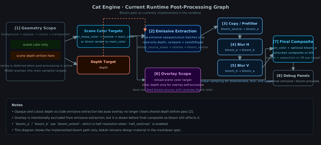
The engine already has an overlay phase (via `OverlayComponent`) and draws overlay batches in [src/engine/graphics/vulkano_cbb.rs](src/engine/graphics/vulkano_cbb.rs).

Important details:

- overlay is drawn after the scene
- depth is cleared before overlay so overlay appears on top
- overlay still depth-tests with itself

A `SCREEN_SPACE_LINES` gizmo material would most likely be used in the **overlay** pass.

## Relationship to “gizmo size in world space”

This doc is about **line thickness**.

You may still want gizmo radius/length to behave like:

- constant world-space size (current approach), or
- constant screen-space size (classic DCC editors), or
- hybrid (clamped min/max).

Those are separate concerns. Clip-space expansion only guarantees constant *thickness*, not constant *overall gizmo size*.

## Recommendation

For gizmos:

- Prefer **Option 2** (perspective position + clip-space expansion) for constant thickness.
- Keep using overlay pass for draw ordering.

This gives “correct 3D placement” while making the gizmo’s stroke width stable across camera changes.