Expand description
§cadrum
cadrum is a Rust CAD crate using statically-linked, headless OpenCASCADE. Runs natively and in WebAssembly.


| primitives | write read | transform | boolean |
|---|---|---|---|
 |  |  |  |
| extrude | loft | sweep | shell |
 |  |  |  |
| bspline | fillet | chamfer | multiview |
 |  |  |  |
§What is cadrum
cadrum is a Rust library for building parametric 3D CAD models. It is
designed to be a clean, scriptable foundation for scientific and engineering
work — short, deterministic Rust programs that produce high-quality solid
geometry.
cadrum has several goals:
- Parametric and scriptable.
Models are ordinary Rust values, so dimensions and topology are driven by code, not a GUI. - Single-binary redistribution.
cadrum ships statically linkable OpenCASCADE binaries, so a build links OCCT in with no system install and redistributes as one self-contained binary. - Runs in the browser.
cadrum also ships a static OpenCASCADE build for thewasm32-unknown-unknowntarget, making it well suited to running what you build directly in the browser via WebAssembly.
Live demo — STEP → glTF converted entirely in-browser (source).

- Fully headless.
No GUI, no windowing, no OS-specific dependencies — cadrum is pure geometry and I/O, suitable for servers, CI, and wasm. - Major formats in and out.
Reads and writes STEP and BRep, and exports glTF (.glb), STL, and PNG — so models flow into CAD tools, web / three.js viewers, 3D printers, and docs.
§Build
Add this to your Cargo.toml:
[dependencies]
cadrum = "^0.8"
cargo build automatically downloads a prebuilt OCCT 8.0.0 binary for these targets:
| Target | Prebuilt OCCT | |
|---|---|---|
 | x86_64-unknown-linux-gnu | ✅ |
| aarch64-unknown-linux-gnu | ✅ |
 | x86_64-pc-windows-msvc | ✅ |
| x86_64-pc-windows-gnu | ✅ |
 | aarch64-apple-darwin | ✅ |
| x86_64-apple-darwin | ✅ |
 | wasm32-unknown-unknown | ✅ (build in Docker) |
Native targets build with a plain cargo build — no system OpenCASCADE install,
no C++ toolchain setup. wasm32-unknown-unknown additionally needs a wasi-sdk
C/C++ toolchain to compile cadrum’s OCCT wrapper, so build it in Docker (below).
§Building for wasm32-unknown-unknown
We ship the wasi-sdk toolchain as a ready-to-use Docker image,
ghcr.io/lzpel/cross-wasm32-unknown-unknown (built from
docker/Dockerfile_wasm32-unknown-unknown)
— so you don’t install wasi-sdk locally. Mount your project and build as usual:
docker run --rm -v "$PWD":/work -w /work ghcr.io/lzpel/cross-wasm32-unknown-unknown cargo build --release
# → target/wasm32-unknown-unknown/release/<your-crate>.wasm
The image cross-compiles to wasm32-unknown-unknown by default; you get a .wasm
from a binary or a crate-type = ["cdylib"] crate (a plain lib produces an .rlib).
Code requirement: run cadrum’s wasm init once at startup, before the first cadrum
call (e.g. from a #[wasm_bindgen(start)] function) — otherwise OCCT’s C++ constructors
never run and the call traps:
cadrum::__anchor_wasi_stub();
unsafe extern "C" {
    fn __wasm_call_ctors();
}
unsafe { __wasm_call_ctors() };
Then run the output through wasm-bindgen / wasm-pack for browser glue. See
opencascade-wasm32-unknown-unknown-example for a complete setup.
Runtime requirement: the module is built with Wasm exception handling
(-fwasm-exceptions, the legacy encoding), so it needs a runtime that supports the
Wasm exception-handling proposal — any current browser, or Node (no
--experimental-wasm-exnref flag required).
§Building for other targets
For a target without a prebuilt OCCT, build OCCT from source:
OCCT_ROOT=/path/to/occt cargo build --features sourceIf OCCT_ROOT is unset, the source build is cached under target/. Requires a
C++17 compiler (GCC, Clang, or MSVC) and CMake.
§Capabilities
| Area | Methods |
|---|---|
| Primitives | Solid::cube, Solid::sphere, Solid::cylinder, Solid::cone, Solid::torus, Solid::half_space |
| Curves | Edge::line, Edge::arc_3pts, Edge::circle, Edge::polygon, Edge::helix, Edge::bspline |
| Surfacing | Solid::extrude, Solid::sweep, Solid::loft, Solid::bspline |
| Editing | Solid::shell, Solid::fillet_edges, Solid::chamfer_edges, Solid::clean |
| Queries | Solid::volume, Solid::area, Solid::center, Solid::inertia, Solid::bounding_box, Solid::contains |
| Topology | Solid::iter_face, Solid::iter_edge, Face::iter_edge, Face::project, Edge::project |
| Identity / history | Solid::id, Face::id, Edge::id, Solid::iter_history |
| I/O | Solid::read_step / Solid::write_step, Solid::read_brep / Solid::write_brep (BRep = OCCT’s BinTools binary format) |
| Mesh | Solid::mesh → Mesh, Mesh::write_stl, Mesh::write_gltf_binary, Mesh::scene → Scene2D, Scene2D::write_svg, Scene2D::write_png (png), Solid::write_multiview_png (png) |
Color (feature color) | per-face and per-solid color preserved across STEP / BRep / STL / glTF / SVG round-trips |
§Features
color(default): EnablesSolid::colorand colormap propagation through STEP / BRep / STL / glTF / SVG I/O via OCCT’s XDE document model. Disable for a smaller binary if shape color is irrelevant.png(default): PNG raster output —Scene2D::write_pngandSolid::write_multiview_png— via the pure-Rusttiny-skiarasterizer. Disable to drop thetiny-skiadependency when SVG / STL / glTF output is enough.source: Build OCCT from upstream sources with CMake instead of downloading a prebuilt tarball. Off by default — most users use the prebuilt path. Enable it for targets that have no published prebuilt.
§Examples
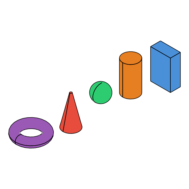
§Primitives
Primitive solids: box, cylinder, sphere, cone, torus — colored and exported as STEP + SVG.
cargo run --example 01_primitives//! Primitive solids: box, cylinder, sphere, cone, torus — colored and exported as STEP + SVG.
use cadrum::{DVec3, Solid};
fn main() -> Result<(), cadrum::Error> {
let example_name = std::path::Path::new(file!()).file_stem().unwrap().to_str().unwrap();
let solids = [Solid::cube(DVec3::ZERO, DVec3::new(10.0, 20.0, 30.0)).color("#4a90d9"), Solid::cylinder(8.0, DVec3::Z * 30.0).translate(DVec3::X * 30.0).color("#e67e22"), Solid::sphere(8.0).translate(DVec3::X * 60.0 + DVec3::Z * 15.0).color("#2ecc71"), Solid::cone(8.0, 1.0, DVec3::Z * 30.0).translate(DVec3::X * 90.0).color("#e74c3c"), Solid::torus(12.0, 4.0, DVec3::Z).translate(DVec3::X * 130.0 + DVec3::Z * 15.0).color("#9b59b6")];
Solid::write_step(&solids, &mut std::fs::File::create(format!("{example_name}.step")).unwrap())?;
let mesh = Solid::mesh(&solids, Default::default())?;
let scene = mesh.scene(Default::default());
scene.write_svg(&mut std::fs::File::create(format!("{example_name}.svg")).unwrap())?;
scene.write_png([640, 640], &mut std::fs::File::create(format!("{example_name}.png")).unwrap())?;
mesh.write_stl(&mut std::fs::File::create(format!("{example_name}.stl")).unwrap())?;
mesh.write_gltf_binary(&mut std::fs::File::create(format!("{example_name}.glb")).unwrap())?;
println!("wrote {example_name}.step / {example_name}.svg / {example_name}.png");
Ok(())
}
Output: 01_primitives.png | 01_primitives.step | 01_primitives.glb | 01_primitives.stl | 01_primitives.svg

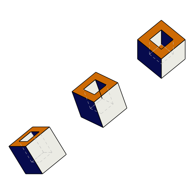
§Write read
Read and write: chain STEP and BRep round-trips with progressive rotation.
cargo run --example 02_write_read//! Read and write: chain STEP and BRep round-trips with progressive rotation.
use cadrum::{DVec3, Solid};
use std::f64::consts::FRAC_PI_8;
fn main() -> Result<(), cadrum::Error> {
let example_name = std::path::Path::new(file!()).file_stem().unwrap().to_str().unwrap();
let step_path = format!("{example_name}.step");
let brep_path = format!("{example_name}.brep");
// 0. Original: read colored_box.step
let manifest_dir = env!("CARGO_MANIFEST_DIR");
let original = Solid::read_step(&mut std::fs::File::open(format!("{manifest_dir}/steps/colored_box.step")).expect("open file"))?;
// 1. STEP round-trip: rotate 30° → write → read
let a_written: Vec<Solid> = original.clone().into_iter().map(|s| s.rotate_x(FRAC_PI_8)).collect();
Solid::write_step(&a_written, &mut std::fs::File::create(&step_path).expect("create file"))?;
let a = Solid::read_step(&mut std::fs::File::open(&step_path).expect("open file"))?;
// 2. BRep round-trip: rotate another 30° → write → read
let b_written: Vec<Solid> = a.clone().into_iter().map(|s| s.rotate_x(FRAC_PI_8)).collect();
Solid::write_brep(&b_written, &mut std::fs::File::create(&brep_path).expect("create file"))?;
let b = Solid::read_brep(&mut std::fs::File::open(&brep_path).expect("open file"))?;
// 3. Arrange side by side and export SVG + STL
let [min, max] = original[0].bounding_box();
let spacing = (max - min).length() * 1.5;
let all: Vec<Solid> = [original, a, b].into_iter().enumerate().flat_map(|(i, solids)| solids.into_iter().map(move |s| s.translate(DVec3::X * spacing * i as f64))).collect();
let mesh = Solid::mesh(&all, Default::default())?;
let scene = mesh.scene(cadrum::SceneOption { view: DVec3::new(1.0, 1.0, 2.0), ..Default::default() });
scene.write_svg(&mut std::fs::File::create(format!("{example_name}.svg")).unwrap())?;
scene.write_png([640, 640], &mut std::fs::File::create(format!("{example_name}.png")).unwrap())?;
mesh.write_stl(&mut std::fs::File::create(format!("{example_name}.stl")).unwrap())?;
mesh.write_gltf_binary(&mut std::fs::File::create(format!("{example_name}.glb")).unwrap())?;
// 4. Print summary
let stl_path = format!("{example_name}.stl");
for (label, path) in [("STEP", &step_path), ("BRep", &brep_path), ("STL", &stl_path)] {
let size = std::fs::metadata(path).map(|m| m.len()).unwrap_or(0);
println!("{label:12} {path:30} {size:>8} bytes");
}
Ok(())
}
Output: 02_write_read.png | 02_write_read.step | 02_write_read.glb | 02_write_read.brep | 02_write_read.stl | 02_write_read.svg

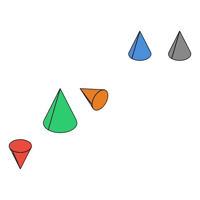
§Transform
Transform operations: translate, rotate, scale, and mirror applied to a cone.
cargo run --example 03_transform//! Transform operations: translate, rotate, scale, and mirror applied to a cone.
use cadrum::{DVec3, Solid};
use std::f64::consts::PI;
fn main() -> Result<(), cadrum::Error> {
let example_name = std::path::Path::new(file!()).file_stem().unwrap().to_str().unwrap();
let base = Solid::cone(8.0, 0.0, DVec3::Z * 20.0).color("#888888");
let solids = [
// original — reference, no transform
base.clone(),
// translate — shift +20 along Z
base.clone().color("#4a90d9").translate(DVec3::X * 40.0 + DVec3::Z * 20.0),
// rotate — 90° around X axis so the cone tips toward Y
base.clone().color("#e67e22").rotate_x(PI / 2.0).translate(DVec3::X * 80.0),
// scaled — 1.5x from its local origin
base.clone().color("#2ecc71").scale(DVec3::ZERO, 1.5).translate(DVec3::X * 120.0),
// mirror — flip across Z=0 plane so the tip points down
base.clone().color("#e74c3c").mirror(DVec3::ZERO, DVec3::Z).translate(DVec3::X * 160.0),
];
Solid::write_step(&solids, &mut std::fs::File::create(format!("{example_name}.step")).unwrap())?;
let mesh = Solid::mesh(&solids, Default::default())?;
let scene = mesh.scene(Default::default());
scene.write_svg(&mut std::fs::File::create(format!("{example_name}.svg")).unwrap())?;
scene.write_png([640, 640], &mut std::fs::File::create(format!("{example_name}.png")).unwrap())?;
mesh.write_stl(&mut std::fs::File::create(format!("{example_name}.stl")).unwrap())?;
mesh.write_gltf_binary(&mut std::fs::File::create(format!("{example_name}.glb")).unwrap())?;
println!("wrote {example_name}.step / {example_name}.svg / {example_name}.png");
Ok(())
}
Output: 03_transform.png | 03_transform.step | 03_transform.glb | 03_transform.stl | 03_transform.svg

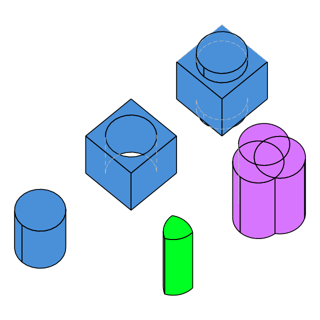
§Boolean
Boolean operations: union, subtract, and intersect between a box and a cylinder.
cargo run --example 04_boolean//! Boolean operations: union, subtract, and intersect between a box and a cylinder.
use cadrum::{Boolean, DVec3, Solid};
fn main() -> Result<(), cadrum::Error> {
let example_name = std::path::Path::new(file!()).file_stem().unwrap().to_str().unwrap();
let make_box = Solid::cube(DVec3::ZERO, DVec3::splat(20.0)).translate(DVec3::X * -10. + DVec3::Y * -10.).color("#4a90d9");
let make_cyl = Solid::cylinder(8.0, DVec3::Z * 30.0).translate(DVec3::Z * -5.);
// union: merge both shapes into one — offset X=0
let union: Solid = (&make_box + &make_cyl).build()?;
// subtract: box minus cylinder — offset X=40
let subtract: Solid = (&make_box - &make_cyl).build()?;
// intersect: only the overlapping volume — offset X=80
let intersect: Solid = (&make_box * &make_cyl).build()?;
let cylinder = Solid::cylinder(8.0, DVec3::Z * 30.0).translate(DVec3::X * 4.);
let [cylinder0, cylinder1, cylinder2] = [cylinder.clone(), cylinder.clone().rotate_z(std::f64::consts::TAU / 3.), cylinder.clone().rotate_z(-std::f64::consts::TAU / 3.)];
// union of all cylinders (fold from Boolean::default() = ⊥)
let sum: Solid = [&cylinder0, &cylinder1, &cylinder2].into_iter().map(Boolean::from).reduce(|a, s| a + s).unwrap().build()?;
let sum = sum.color("#d875ff");
// intersection of all cylinders (reduce — intersect has no fixed init)
let product: Solid = [&cylinder0, &cylinder1, &cylinder2].into_iter().map(Boolean::from).reduce(|a, b| a * b).unwrap().build()?;
let product = product.color("#00ff22");
let shapes = [union.translate(DVec3::X * 0.0), subtract.translate(DVec3::X * 40.0), intersect.translate(DVec3::X * 80.0), sum.translate(DVec3::X * 20.0 + DVec3::Y * 40.0), product.translate(DVec3::X * 60.0 + DVec3::Y * 40.0)];
Solid::write_step(&shapes, &mut std::fs::File::create(format!("{example_name}.step")).unwrap())?;
let mesh = Solid::mesh(&shapes, Default::default())?;
let scene = mesh.scene(cadrum::SceneOption { view: DVec3::new(1.0, 1.0, 2.0), ..Default::default() });
scene.write_svg(&mut std::fs::File::create(format!("{example_name}.svg")).unwrap())?;
scene.write_png([640, 640], &mut std::fs::File::create(format!("{example_name}.png")).unwrap())?;
mesh.write_stl(&mut std::fs::File::create(format!("{example_name}.stl")).unwrap())?;
mesh.write_gltf_binary(&mut std::fs::File::create(format!("{example_name}.glb")).unwrap())?;
println!("wrote {example_name}.step / {example_name}.svg / {example_name}.png");
Ok(())
}
Output: 04_boolean.png | 04_boolean.step | 04_boolean.glb | 04_boolean.stl | 04_boolean.svg

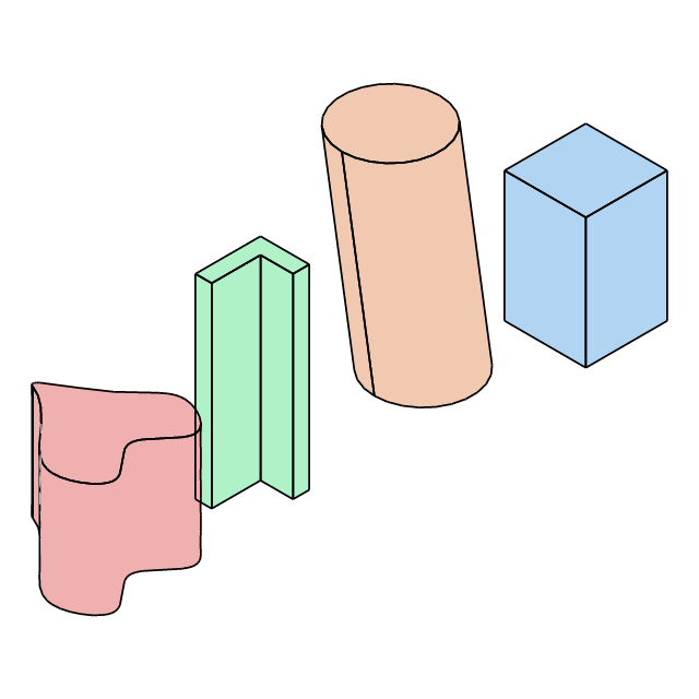
§Extrude
Demo of Solid::extrude: push a closed 2D profile along a direction vector.
cargo run --example 05_extrude//! Demo of `Solid::extrude`: push a closed 2D profile along a direction vector.
//!
//! - **Box**: square polygon extruded along Z
//! - **Oblique cylinder**: circle extruded at a steep angle
//! - **L-beam**: L-shaped polygon extruded along Z
//! - **Heart**: BSpline heart-shaped profile extruded along Z
use cadrum::{BSplineEnd, DVec3, Edge, Error, Solid};
/// Square polygon → box (simplest extrude).
fn build_box() -> Result<Solid, Error> {
let profile = Edge::polygon(&[DVec3::new(0.0, 0.0, 0.0), DVec3::new(5.0, 0.0, 0.0), DVec3::new(5.0, 5.0, 0.0), DVec3::new(0.0, 5.0, 0.0)])?;
Solid::extrude(&profile, DVec3::Z * 8.0)
}
/// Circle extruded at a steep angle → oblique cylinder.
fn build_oblique_cylinder() -> Result<Solid, Error> {
let profile = [Edge::circle(3.0, DVec3::Z)?];
Solid::extrude(&profile, DVec3::new(-4.0, -6.0, 8.0))
}
/// L-shaped polygon → L-beam.
fn build_l_beam() -> Result<Solid, Error> {
let profile = Edge::polygon(&[DVec3::new(0.0, 0.0, 0.0), DVec3::new(4.0, 0.0, 0.0), DVec3::new(4.0, 1.0, 0.0), DVec3::new(1.0, 1.0, 0.0), DVec3::new(1.0, 3.0, 0.0), DVec3::new(0.0, 3.0, 0.0)])?;
Solid::extrude(&profile, DVec3::Z * 12.0)
}
/// Heart-shaped BSpline profile extruded along Z.
fn build_heart() -> Result<Solid, Error> {
let profile = [Edge::bspline(
&[
DVec3::new(0.0, -4.0, 0.0), // bottom tip
DVec3::new(2.0, -1.5, 0.0),
DVec3::new(4.0, 1.5, 0.0),
DVec3::new(2.5, 3.5, 0.0), // right lobe top
DVec3::new(0.0, 2.0, 0.0), // center dip
DVec3::new(-2.5, 3.5, 0.0), // left lobe top
DVec3::new(-4.0, 1.5, 0.0),
DVec3::new(-2.0, -1.5, 0.0),
],
BSplineEnd::Periodic,
)?];
Solid::extrude(&profile, DVec3::Z * 7.0)
}
fn main() -> Result<(), Error> {
let example_name = std::path::Path::new(file!()).file_stem().unwrap().to_str().unwrap();
let box_solid = build_box()?.color("#b0d4f1");
let oblique = build_oblique_cylinder()?.color("#f1c8b0").translate(DVec3::X * 10.0);
let l_beam = build_l_beam()?.color("#b0f1c8").translate(DVec3::X * 20.0);
let heart = build_heart()?.color("#f1b0b0").translate(DVec3::X * 30.0);
let result = [box_solid, oblique, l_beam, heart];
Solid::write_step(&result, &mut std::fs::File::create(format!("{example_name}.step")).unwrap())?;
let mesh = Solid::mesh(&result, Default::default())?;
let scene = mesh.scene(Default::default());
scene.write_svg(&mut std::fs::File::create(format!("{example_name}.svg")).unwrap())?;
scene.write_png([640, 640], &mut std::fs::File::create(format!("{example_name}.png")).unwrap())?;
mesh.write_stl(&mut std::fs::File::create(format!("{example_name}.stl")).unwrap())?;
mesh.write_gltf_binary(&mut std::fs::File::create(format!("{example_name}.glb")).unwrap())?;
println!("wrote {example_name}.step / {example_name}.svg / {example_name}.png");
Ok(())
}
Output: 05_extrude.png | 05_extrude.step | 05_extrude.glb | 05_extrude.stl | 05_extrude.svg

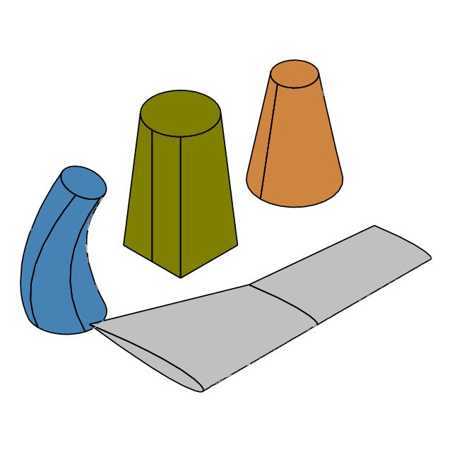
§Loft
Demo of Solid::loft: skin a solid through cross-section wires.
cargo run --example 06_loft//! Demo of `Solid::loft`: skin a solid through cross-section wires.
//!
//! - **Frustum**: two circles of different radii → truncated cone (minimal loft)
//! - **Morph**: square polygon → circle (cross-section shape transition)
//! - **Tilted**: three non-parallel circular sections → twisted loft
//! - **Wing**: three NACA0012 sections lofted with `ruled=true` (straight ruled panels between sections — the sheet-metal / developable variant)
use cadrum::{BSplineEnd, DVec2, DVec3, Edge, Error, Solid};
/// Two circles → frustum (minimal loft example).
fn build_frustum() -> Result<Solid, Error> {
let lower = [Edge::circle(3.0, DVec3::Z)?];
let upper = [Edge::circle(1.5, DVec3::Z)?.translate(DVec3::Z * 8.0)];
Ok(Solid::loft(&[lower, upper], false)?.color("#cd853f"))
}
/// Square polygon → circle (2-section morph loft).
fn build_morph() -> Result<Solid, Error> {
let r = 2.5;
let square = Edge::polygon(&[DVec3::new(-r, -r, 0.0), DVec3::new(r, -r, 0.0), DVec3::new(r, r, 0.0), DVec3::new(-r, r, 0.0)])?;
let circle = Edge::circle(r, DVec3::Z)?.translate(DVec3::Z * 10.0);
Ok(Solid::loft([square.as_slice(), std::slice::from_ref(&circle)], false)?.color("#808000"))
}
/// Three non-parallel circular sections → twisted loft.
fn build_tilted() -> Result<Solid, Error> {
let bottom = [Edge::circle(2.5, DVec3::Z)?];
let mid = [Edge::circle(2.0, DVec3::new(0.3, 0.0, 1.0).normalize())?.translate(DVec3::X + DVec3::Z * 5.0)];
let top = [Edge::circle(1.5, DVec3::new(-0.2, 0.3, 1.0).normalize())?.translate(DVec3::new(-0.5, 1.0, 10.0))];
Ok(Solid::loft(&[bottom, mid, top], false)?.color("#4682b4"))
}
/// NACA0012-like airfoil section points (unit chord, 2D: x = chord, y = thickness).
/// Cosine spacing walks TE → upper → LE → lower → TE, returning a closed loop
/// with the TE point duplicated at the end (a closed section with a sharp TE,
/// interpolated as a NotAKnot open curve).
fn naca_points(n: usize) -> Vec<DVec2> {
let half = |x: f64| 5.0 * 0.12 * (0.2969 * x.sqrt() - 0.1260 * x - 0.3516 * x * x + 0.2843 * x.powi(3) - 0.1036 * x.powi(4));
let upper: Vec<DVec2> = (0..=n)
.map(|i| {
let x = (1.0 + (std::f64::consts::PI * i as f64 / n as f64).cos()) / 2.0;
DVec2::new(x, half(x))
})
.collect();
let lower: Vec<DVec2> = (1..=n)
.map(|i| {
let x = (1.0 - (std::f64::consts::PI * i as f64 / n as f64).cos()) / 2.0;
DVec2::new(x, -half(x))
})
.collect();
[upper, lower].concat()
}
/// Three NACA sections → tapered wing, lofted with `ruled=true` (straight panels).
fn build_wing(scale: f64) -> Result<Solid, Error> {
let stations = [(1.0, 0.0), (0.6, 1.0), (0.5, 2.0)];
let sections: Vec<[Edge; 1]> = stations
.iter()
.map(|&(c, z)| {
let points: Vec<DVec3> = naca_points(60).into_iter().map(|p| DVec3::new(c * p.x, c * p.y, z) * scale).collect();
[Edge::bspline(&points, BSplineEnd::NotAKnot).expect("NACA bspline section")]
})
.collect();
Ok(Solid::loft(§ions, true)?.color("silver"))
}
fn main() -> Result<(), Error> {
let example_name = std::path::Path::new(file!()).file_stem().unwrap().to_str().unwrap();
let frustum = build_frustum()?;
let morph = build_morph()?.translate(DVec3::X * 10.0);
let tilted = build_tilted()?.translate(DVec3::X * 20.0);
let wing = build_wing(10.0)?.align_z(-DVec3::X, -DVec3::Y).translate(DVec3::X * 20.0 + DVec3::Y * 12.0);
let result = [frustum, morph, tilted, wing];
Solid::write_step(&result, &mut std::fs::File::create(format!("{example_name}.step")).unwrap())?;
let mesh = Solid::mesh(&result, Default::default())?;
let scene = mesh.scene(Default::default());
scene.write_svg(&mut std::fs::File::create(format!("{example_name}.svg")).unwrap())?;
scene.write_png([640, 640], &mut std::fs::File::create(format!("{example_name}.png")).unwrap())?;
mesh.write_stl(&mut std::fs::File::create(format!("{example_name}.stl")).unwrap())?;
mesh.write_gltf_binary(&mut std::fs::File::create(format!("{example_name}.glb")).unwrap())?;
println!("wrote {example_name}.step / {example_name}.svg / {example_name}.png");
Ok(())
}
Output: 06_loft.png | 06_loft.step | 06_loft.glb | 06_loft.stl | 06_loft.svg

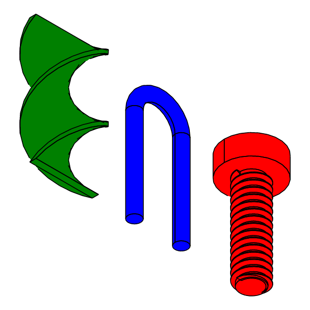
§Sweep
Sweep showcase: M2 screw (helix spine) + U-shaped pipe (line+arc+line spine)
cargo run --example 07_sweep//! Sweep showcase: M2 screw (helix spine) + U-shaped pipe (line+arc+line spine)
//! + twisted ribbon (`Auxiliary` aux-spine mode).
//!
//! `ProfileOrient` controls how the profile is oriented as it travels along the spine:
//!
//! - `Fixed`: profile is parallel-transported without rotating. Cross-sections
//! stay parallel to the starting orientation. Suited for straight extrusions;
//! on a curved spine the profile drifts off the tangent and the result breaks.
//! - `Torsion`: profile follows the spine's principal normal (raw Frenet–Serret
//! frame). Suited for constant-curvature/torsion curves like helices and for
//! 3D free curves where the natural twist should carry into the profile.
//! Fails near inflection points where the principal normal flips.
//! - `Up(axis)`: profile keeps `axis` as its binormal — at every point the
//! profile is rotated around the tangent so one in-plane axis stays in the
//! tangent–`axis` plane. Suited for roads/rails/pipes that must preserve a
//! gravity direction. On a helix, `Up(helix_axis)` is equivalent to `Torsion`.
//! Fails when the tangent becomes parallel to `axis`.
//! - `Auxiliary(aux_spine)`: profile's tracked axis points from the main spine
//! toward a parallel auxiliary spine. Arbitrary twist control — e.g. a
//! helical `aux_spine` on a straight `spine` produces a twisted ribbon.
use cadrum::{DVec3, Edge, Error, ProfileOrient, Solid};
// ==================== Component 1: M2 ISO screw ====================
fn build_m2_screw() -> Result<Solid, Error> {
let r = 1.0;
let h_pitch = 0.4;
let h_thread = 6.0;
let r_head = 1.75;
let h_head = 1.3;
// ISO M thread fundamental triangle height: H = √3/2 · P (sharp 60° triangle).
let r_delta = 3f64.sqrt() / 2.0 * h_pitch;
// Helix spine at the root radius. x_ref=+X anchors the start at (r-r_delta, 0, 0).
let helix = Edge::helix(r - r_delta, h_pitch, h_thread, DVec3::Z, DVec3::X)?;
// Closed triangular profile in local coords (x: radial, y: along helix tangent).
let profile = Edge::polygon(&[DVec3::new(0.0, -h_pitch / 2.0, 0.0), DVec3::new(r_delta, 0.0, 0.0), DVec3::new(0.0, h_pitch / 2.0, 0.0)])?;
// Align profile +Z with the helix start tangent, then translate to the start point.
let profile: Vec<Edge> = profile.into_iter().map(|e| e.align_z(helix.start_tangent(), helix.start_point()).translate(helix.start_point())).collect();
// Sweep along the helix. Up(+Z) ≡ Torsion for a helix and yields a correct thread.
let thread = Solid::sweep(&profile, &[helix], ProfileOrient::Up(DVec3::Z))?;
// Reconstruct the ISO 68-1 basic profile (trapezoid) from the sharp triangle:
// union(shaft) fills the bottom H/4 → P/4-wide flat at the root
// intersect(crest) trims the top H/8 → P/8-wide flat at the crest
let shaft = Solid::cylinder(r - r_delta * 6.0 / 8.0, DVec3::Z * h_thread);
let crest = Solid::cylinder(r - r_delta / 8.0, DVec3::Z * h_thread);
let thread_shaft: Solid = ((&thread + &shaft) * &crest).build()?;
// Stack the flat head on top. Screw ends up centered on the origin.
let head = Solid::cylinder(r_head, DVec3::Z * h_head).translate(DVec3::Z * h_thread);
let res: Solid = (&thread_shaft + &head).build()?;
Ok(res.color("red"))
}
// ==================== Component 2: U-shaped pipe ====================
fn build_u_pipe() -> Result<Solid, Error> {
let pipe_radius = 0.4;
let leg_length = 6.0;
let gap = 3.0;
let half_gap = gap / 2.0;
let bend_radius = half_gap;
// U-shaped path in the XZ plane, centered on origin in X: A↑B ⌒ C↓D.
let a = DVec3::new(-half_gap, 0.0, 0.0);
let b = DVec3::new(-half_gap, 0.0, leg_length);
let arc_mid = DVec3::new(0.0, 0.0, leg_length + bend_radius);
let c = DVec3::new(half_gap, 0.0, leg_length);
let d = DVec3::new(half_gap, 0.0, 0.0);
// Spine wire: line → semicircle → line.
let up_leg = Edge::line(a, b)?;
let bend = Edge::arc_3pts(b, arc_mid, c)?;
let down_leg = Edge::line(c, d)?;
// Circular profile in XY (normal +Z) translated to the spine start `a`.
// Spine tangent at `a` is +Z, so the XY-plane circle is already aligned.
let profile = Edge::circle(pipe_radius, DVec3::Z)?.translate(a);
// Up(+Y) fixes the binormal to the path-plane normal, avoiding Frenet
// degeneracy on the straight segments.
let pipe = Solid::sweep(&[profile], &[up_leg, bend, down_leg], ProfileOrient::Up(DVec3::Y))?;
Ok(pipe.translate(DVec3::X * 6.0).color("blue"))
}
// ==================== Component 3: Auxiliary-spine twisted ribbon ====================
// Sweeping a straight spine with `Auxiliary(&[helix])` rotates the tracked
// axis of the profile at each point to face the corresponding helix point.
// A pitch=h helix makes exactly one 360° turn over [0, h], so a flat
// rectangular profile becomes a ribbon twisted once. With `Fixed` or
// `Torsion` the profile wouldn't rotate along a straight spine — visible
// twist is therefore proof that Auxiliary is in effect.
fn build_twisted_ribbon() -> Result<Solid, Error> {
let h = 8.0;
let aux_r = 3.0;
let spine = Edge::line(DVec3::ZERO, DVec3::Z * h)?;
let aux = Edge::helix(aux_r, h, h, DVec3::Z, DVec3::X)?;
// Flat rectangle (10:1 aspect) — circles or squares wouldn't reveal any twist.
let profile = Edge::polygon(&[DVec3::new(-2.0, -0.2, 0.0), DVec3::new(2.0, -0.2, 0.0), DVec3::new(2.0, 0.2, 0.0), DVec3::new(-2.0, 0.2, 0.0)])?;
let ribbon = Solid::sweep(&profile, &[spine], ProfileOrient::Auxiliary(&[aux]))?;
Ok(ribbon.translate(DVec3::X * 12.0).color("green"))
}
// ==================== main: side-by-side layout ====================
//
// Each builder places its component at its final world position (screw at
// origin, U-pipe at x=6, ribbon at x=12) and applies its color, so main
// just concatenates them.
fn main() -> Result<(), Error> {
let example_name = std::path::Path::new(file!()).file_stem().unwrap().to_str().unwrap();
let all = [build_m2_screw()?, build_u_pipe()?, build_twisted_ribbon()?];
Solid::write_step(&all, &mut std::fs::File::create(format!("{example_name}.step")).unwrap())?;
// Helical threads have dense hidden lines that clutter the output; disable them.
let mesh = Solid::mesh(&all, Default::default())?;
let scene = mesh.scene(cadrum::SceneOption { view: DVec3::new(1.0, 1.0, -1.0), hidden_edges: false, ..Default::default() });
scene.write_svg(&mut std::fs::File::create(format!("{example_name}.svg")).unwrap())?;
scene.write_png([640, 640], &mut std::fs::File::create(format!("{example_name}.png")).unwrap())?;
mesh.write_stl(&mut std::fs::File::create(format!("{example_name}.stl")).unwrap())?;
mesh.write_gltf_binary(&mut std::fs::File::create(format!("{example_name}.glb")).unwrap())?;
println!("wrote {example_name}.step / {example_name}.svg / {example_name}.png ({} solids)", all.len());
Ok(())
}
Output: 07_sweep.png | 07_sweep.step | 07_sweep.glb | 07_sweep.stl | 07_sweep.svg

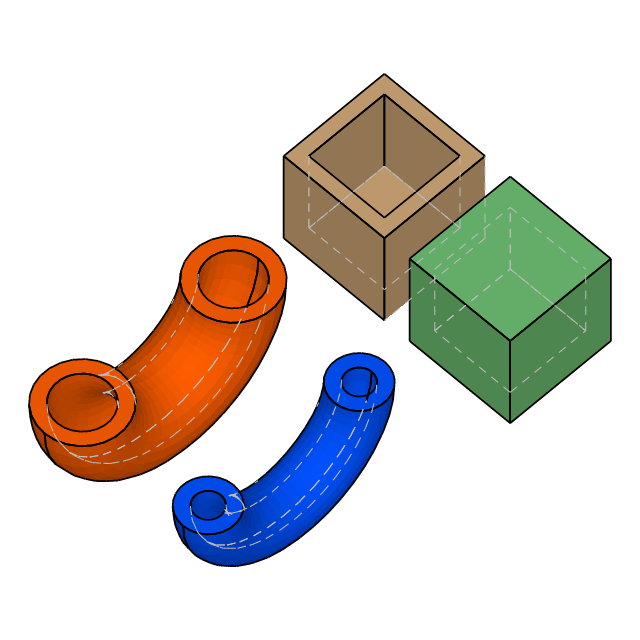
§Shell
Demo of Solid::shell:
cargo run --example 08_shell//! Demo of `Solid::shell`:
//! - Cube: remove top face, offset inward → open-top container
//! - Sealed cube: empty open_faces → solid with an internal void (outer skin
//! + reversed inner shell)
//! - Torus: bisect with a half-space to introduce planar cut faces, then
//! shell using those cut faces as the openings → thin-walled half-ring
//! with both cross-sections exposed
use cadrum::{DVec3, Error, Solid};
fn hollow_cube() -> Result<Solid, Error> {
let cube = Solid::cube(DVec3::ZERO, DVec3::splat(8.0));
// TopExp_Explorer order on a box is stable; +Z face ends up last.
let top = cube.iter_face().last().expect("cube has faces");
cube.shell(-1.0, [top])
}
fn sealed_cube() -> Result<Solid, Error> {
let cube = Solid::cube(DVec3::ZERO, DVec3::splat(8.0));
cube.shell(-1.0, std::iter::empty::<&cadrum::Face>())
}
fn halved_shelled_torus(thickness: f64) -> Result<Solid, Error> {
let torus = Solid::torus(6.0, 2.0, DVec3::Y);
// Bisect with Y=0 half-space (normal +Y): keep the +Y half of the ring — always 1 solid.
let cutter = Solid::half_space(DVec3::ZERO, -DVec3::Z);
// `iter_history()` yields [post_id, src_id] pairs for every result face.
// Filter to those whose src_id is one of the cutter's faces, then collect
// their post_ids — these are the planar cut faces in the result that we
// want to use as shell openings.
let cutter_face_ids: std::collections::HashSet<u64> = cutter.iter_face().map(|f| f.id()).collect();
let half: Solid = (&torus * &cutter).build()?;
let from_cutter: std::collections::HashSet<u64> = half.iter_history().filter_map(|[post, src]| cutter_face_ids.contains(&src).then_some(post)).collect();
half.shell(thickness, half.iter_face().filter(|f| from_cutter.contains(&f.id())))
}
fn main() -> Result<(), Error> {
let example_name = std::path::Path::new(file!()).file_stem().unwrap().to_str().unwrap();
let result = [hollow_cube()?.color("#d0a878"), sealed_cube()?.color("#6fbf73").translate(DVec3::Y * 10.0), halved_shelled_torus(1.0)?.color("#ff5e00").translate(DVec3::X * 18.0), halved_shelled_torus(-1.0)?.color("#0052ff").translate(DVec3::X * 18.0 + DVec3::Y * 10.0)];
Solid::write_step(&result, &mut std::fs::File::create(format!("{example_name}.step")).unwrap())?;
// Isometric view from (1, 1, 2) with shading so the cavity depth reads
// naturally.
let mesh = Solid::mesh(&result, Default::default())?;
let scene = mesh.scene(cadrum::SceneOption { view: DVec3::new(1.0, 1.0, 2.0), shading: true, ..Default::default() });
scene.write_svg(&mut std::fs::File::create(format!("{example_name}.svg")).unwrap())?;
scene.write_png([640, 640], &mut std::fs::File::create(format!("{example_name}.png")).unwrap())?;
mesh.write_stl(&mut std::fs::File::create(format!("{example_name}.stl")).unwrap())?;
mesh.write_gltf_binary(&mut std::fs::File::create(format!("{example_name}.glb")).unwrap())?;
println!("wrote {example_name}.step / {example_name}.svg / {example_name}.png");
Ok(())
}
Output: 08_shell.png | 08_shell.step | 08_shell.glb | 08_shell.stl | 08_shell.svg

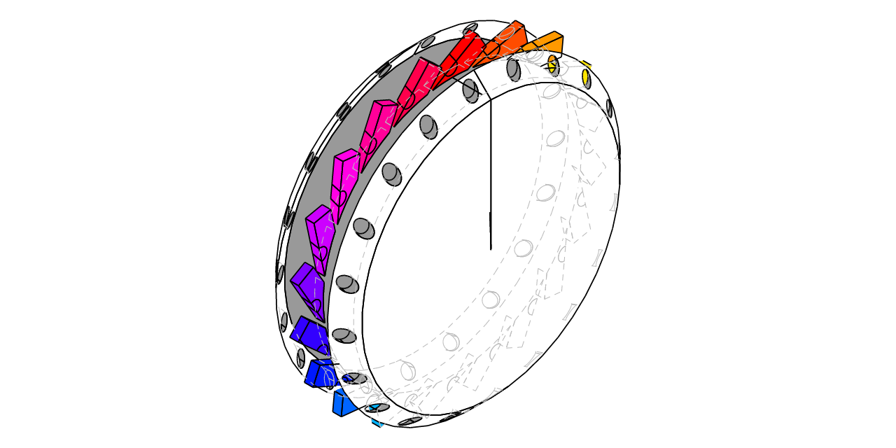
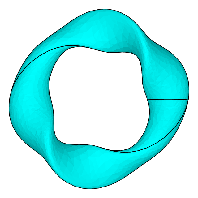
§Bspline
cargo run --example 09_bsplineuse cadrum::{DQuat, DVec3, Solid};
use std::f64::consts::TAU;
// 2 field-period stellarator-like torus.
// `Solid::bspline` is fed a 2D control-point grid to build a periodic B-spline solid.
// Every variation below is invariant under phi → phi+π (or shifts by a multiple
// of 2π), so the resulting shape has 180° rotational symmetry around the Z axis:
// a(phi) = 1.8 + 0.6 * sin(2φ) radial semi-axis
// b(phi) = 1.0 + 0.4 * cos(2φ) Z semi-axis
// psi(phi) = 2 * phi cross-section twist (2 turns per loop)
// z_shift(phi) = 1.0 * sin(2φ) vertical undulation
const M: usize = 48; // toroidal (U) — must be even for 180° symmetry
const N: usize = 24; // poloidal (V) — arbitrary
const RING_R: f64 = 6.0;
fn point(i: usize, j: usize) -> DVec3 {
let phi = TAU * (i as f64) / (M as f64);
let theta = TAU * (j as f64) / (N as f64);
let two_phi = 2.0 * phi;
let a = 1.8 + 0.6 * two_phi.sin();
let b = 1.0 + 0.4 * two_phi.cos();
let psi = two_phi; // twist: 2 full turns per toroidal loop
let z_shift = 1.0 * two_phi.sin();
// 1. Local cross-section (pre-twist ellipse in the (X, Z) plane)
let local_raw = DVec3::X * (a * theta.cos()) + DVec3::Z * (b * theta.sin());
// 2. Rotate by psi around the local Y axis (major-circle tangent) — the twist
let local_twisted = DQuat::from_axis_angle(DVec3::Y, psi) * local_raw;
// 3. Undulate vertically in the local frame
let local_shifted = local_twisted + DVec3::Z * z_shift;
// 4. Push outward along the major radius by RING_R
let translated = local_shifted + DVec3::X * RING_R;
// 5. Rotate the whole point around the global Z axis by phi
DQuat::from_axis_angle(DVec3::Z, phi) * translated
}
fn main() -> Result<(), cadrum::Error> {
let example_name = std::path::Path::new(file!()).file_stem().unwrap().to_str().unwrap();
let plasma = Solid::bspline(M, N, true, point).expect("2-period bspline torus should succeed");
let objects = [plasma.color("cyan")];
Solid::write_step(&objects, &mut std::fs::File::create(format!("{example_name}.step")).unwrap())?;
let mesh = Solid::mesh(&objects, Default::default())?;
let scene = mesh.scene(cadrum::SceneOption { view: DVec3::new(0.05, 0.05, 1.0), up: DVec3::Y, hidden_edges: false, shading: true });
scene.write_svg(&mut std::fs::File::create(format!("{example_name}.svg")).unwrap())?;
scene.write_png([640, 640], &mut std::fs::File::create(format!("{example_name}.png")).unwrap())?;
mesh.write_stl(&mut std::fs::File::create(format!("{example_name}.stl")).unwrap())?;
mesh.write_gltf_binary(&mut std::fs::File::create(format!("{example_name}.glb")).unwrap())?;
println!("wrote {example_name}.step / {example_name}.svg / {example_name}.png");
Ok(())
}
Output: 09_bspline.png | 09_bspline.step | 09_bspline.glb | 09_bspline.stl | 09_bspline.svg

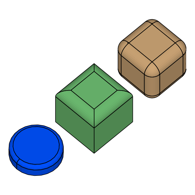
§Fillet
Demo of Solid::fillet_edges:
cargo run --example 10_fillet//! Demo of `Solid::fillet_edges`:
//! - All 12 cube edges filleted uniformly (rounded cube)
//! - Only top 4 edges filleted (soft top, sharp base)
//! - Cylinder top circular edge filleted (coin shape)
use cadrum::{DVec3, Error, Solid};
fn rounded_cube(size: f64) -> Result<Solid, Error> {
let cube = Solid::cube(DVec3::ZERO, DVec3::splat(size)).translate(-DVec3::ONE * (size / 2.0));
let radius = size * 0.2;
cube.fillet_edges(radius, cube.iter_edge())
}
fn soft_top_cube(size: f64) -> Result<Solid, Error> {
let cube = Solid::cube(DVec3::ZERO, DVec3::splat(size)).translate(-DVec3::ONE * (size / 2.0));
let radius = size * 0.2;
// Top cap boundary: a closed circular edge whose start == end lives at z = h.
let top_edges = cube.iter_edge().filter(|e| [e.start_point(), e.end_point()].iter().all(|p| (p.z - size / 2.0).abs() < 1e-6));
cube.fillet_edges(radius, top_edges)
}
fn coin(radius: f64, height: f64) -> Result<Solid, Error> {
let cyl = Solid::cylinder(radius, DVec3::Z * height);
let radius = height * 0.3;
// Top cap boundary: a closed circular edge whose start == end lives at z = h.
let top_circle = cyl.iter_edge().filter(|e| [e.start_point(), e.end_point()].iter().all(|p| (p.z - height).abs() < 1e-6));
cyl.fillet_edges(radius, top_circle)
}
fn main() -> Result<(), Error> {
let example_name = std::path::Path::new(file!()).file_stem().unwrap().to_str().unwrap();
let result = [rounded_cube(8.0)?.color("#d0a878"), soft_top_cube(8.0)?.color("#6fbf73").translate(DVec3::X * 12.0), coin(4.0, 2.0)?.color("#0052ff").translate(DVec3::X * 24.0)];
Solid::write_step(&result, &mut std::fs::File::create(format!("{example_name}.step")).unwrap())?;
let mesh = Solid::mesh(&result, Default::default())?;
let scene = mesh.scene(cadrum::SceneOption { view: DVec3::new(1.0, 1.0, 2.0), shading: true, ..Default::default() });
scene.write_svg(&mut std::fs::File::create(format!("{example_name}.svg")).unwrap())?;
scene.write_png([640, 640], &mut std::fs::File::create(format!("{example_name}.png")).unwrap())?;
mesh.write_stl(&mut std::fs::File::create(format!("{example_name}.stl")).unwrap())?;
mesh.write_gltf_binary(&mut std::fs::File::create(format!("{example_name}.glb")).unwrap())?;
println!("wrote {example_name}.step / {example_name}.svg / {example_name}.png");
Ok(())
}
Output: 10_fillet.png | 10_fillet.step | 10_fillet.glb | 10_fillet.stl | 10_fillet.svg

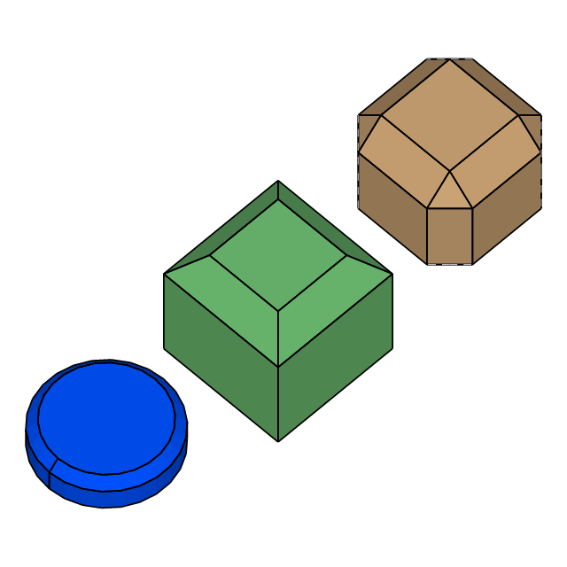
§Chamfer
Demo of Solid::chamfer_edges — mirror of 10_fillet.rs using bevels:
cargo run --example 11_chamfer//! Demo of `Solid::chamfer_edges` — mirror of `10_fillet.rs` using bevels:
//! - All 12 cube edges chamfered uniformly (beveled cube)
//! - Only top 4 edges chamfered (soft top, sharp base)
//! - Cylinder top circular edge chamfered (coin with beveled rim)
use cadrum::{DVec3, Error, Solid};
fn beveled_cube(size: f64) -> Result<Solid, Error> {
let cube = Solid::cube(DVec3::ZERO, DVec3::splat(size)).translate(-DVec3::ONE * (size / 2.0));
let distance = size * 0.2;
cube.chamfer_edges(distance, cube.iter_edge())
}
fn beveled_top_cube(size: f64) -> Result<Solid, Error> {
let cube = Solid::cube(DVec3::ZERO, DVec3::splat(size)).translate(-DVec3::ONE * (size / 2.0));
let distance = size * 0.2;
// Top cap boundary: a closed circular edge whose start == end lives at z = h.
let top_edges = cube.iter_edge().filter(|e| [e.start_point(), e.end_point()].iter().all(|p| (p.z - size / 2.0).abs() < 1e-6));
cube.chamfer_edges(distance, top_edges)
}
fn beveled_coin(radius: f64, height: f64) -> Result<Solid, Error> {
let cyl = Solid::cylinder(radius, DVec3::Z * height);
let distance = height * 0.3;
// Top cap boundary: a closed circular edge whose start == end lives at z = h.
let top_circle = cyl.iter_edge().filter(|e| [e.start_point(), e.end_point()].iter().all(|p| (p.z - height).abs() < 1e-6));
cyl.chamfer_edges(distance, top_circle)
}
fn main() -> Result<(), Error> {
let example_name = std::path::Path::new(file!()).file_stem().unwrap().to_str().unwrap();
let result = [beveled_cube(8.0)?.color("#d0a878"), beveled_top_cube(8.0)?.color("#6fbf73").translate(DVec3::X * 12.0), beveled_coin(4.0, 2.0)?.color("#0052ff").translate(DVec3::X * 24.0)];
Solid::write_step(&result, &mut std::fs::File::create(format!("{example_name}.step")).unwrap())?;
let mesh = Solid::mesh(&result, Default::default())?;
let scene = mesh.scene(cadrum::SceneOption { view: DVec3::new(1.0, 1.0, 2.0), shading: true, ..Default::default() });
scene.write_svg(&mut std::fs::File::create(format!("{example_name}.svg")).unwrap())?;
scene.write_png([640, 640], &mut std::fs::File::create(format!("{example_name}.png")).unwrap())?;
mesh.write_stl(&mut std::fs::File::create(format!("{example_name}.stl")).unwrap())?;
mesh.write_gltf_binary(&mut std::fs::File::create(format!("{example_name}.glb")).unwrap())?;
println!("wrote {example_name}.step / {example_name}.svg / {example_name}.png");
Ok(())
}
Output: 11_chamfer.png | 11_chamfer.step | 11_chamfer.glb | 11_chamfer.stl | 11_chamfer.svg

§Multiview
Fixed 4-view multiview PNG for LLM-driven design loops.
cargo run --example 12_multiview//! Fixed 4-view multiview PNG for LLM-driven design loops.
//!
//! A single call to `Solid::write_multiview_png` produces a 1024×1024 PNG that lays out
//! 4 views — ISO plus the axis cyclic order (+X / +Y / +Z) — at the same scale. With no
//! parameters to tune, Solid maps 1:1 to an image, which suits state-snapshot rendering
//! for LLMs and automated design loops.
use cadrum::{DVec3, Solid};
fn main() -> Result<(), cadrum::Error> {
let example_name = std::path::Path::new(file!()).file_stem().unwrap().to_str().unwrap();
let block = Solid::cube(DVec3::ZERO, DVec3::new(40.0, 30.0, 20.0)).translate(-DVec3::new(20.0, 15.0, 10.0));
let hole = Solid::cylinder(5.0, DVec3::Z * 30.0).translate(-DVec3::Z * 15.0);
// Axis-orientation check: carve only the +X+Y+Z corner with a sphere.
// Which corner the notch appears in on each panel uniquely confirms the gnomon's direction.
let corner_cut = Solid::sphere(10.0).translate(DVec3::new(20.0, 15.0, 10.0));
let part: Solid = (&block - &hole - &corner_cut).build()?;
part.write_multiview_png(&mut std::fs::File::create(format!("{example_name}.png")).unwrap())?;
let mesh = Solid::mesh([&part], Default::default())?;
mesh.write_stl(&mut std::fs::File::create(format!("{example_name}.stl")).unwrap())?;
mesh.write_gltf_binary(&mut std::fs::File::create(format!("{example_name}.glb")).unwrap())?;
println!("wrote {example_name}.png / {example_name}.stl / {example_name}.glb");
Ok(())
}
Output: 12_multiview.png | 12_multiview.glb | 12_multiview.stl
§The Type Map
Three concrete shape types form the whole public surface — there are no collection wrapper traits:
    Edge  ── single 3D curve         ┐
    Face  ── trimmed 3D surface      │ concrete BRep handles
    Solid ── connected closed body   ┘
Every method is inherent on the concrete type — no trait import is ever needed:
let s = Solid::cube(DVec3::ZERO, DVec3::ONE).rotate_z(0.5).translate(DVec3::X);
let v = s.volume();§Errors
Every fallible operation returns Result<T, Error> with Error
enumerating the failure modes (Error::SweepFailed,
Error::FilletFailed, Error::InvalidEdge, etc.). Variants that need
detail carry a String payload identifying which constructor or parameter
combination tripped OCCT, so panics are reserved for true logic bugs.
§License
This project is licensed under the MIT License.
Compiled binaries include OpenCASCADE Technology (OCCT), which is licensed under the LGPL 2.1. Users who distribute applications built with cadrum must comply with the LGPL 2.1 terms. Since cadrum builds OCCT from source, end users can rebuild and relink OCCT to satisfy this requirement.
Re-exports§
pub use occt::edge::Edge;pub use occt::face::Face;pub use occt::solid::Solid;pub use common::color::Color;pub use common::boolean::Boolean;pub use common::error::Error;pub use common::mesh::Mesh;pub use common::mesh::Scene2D;pub use common::mesh::SceneOption;pub use glam;
Modules§
Structs§
- DMat3
- A 3x3 column major matrix.
- DMat4
- A 4x4 column major matrix.
- DQuat
- A quaternion representing an orientation.
- DVec2
- A 2-dimensional vector.
- DVec3
- A 3-dimensional vector.
- Tessellation
- Tessellation parameters for
Solid::meshandEdge::approximation_segments.
Enums§
- BSpline
End - End-condition selector for [
EdgeStruct::bspline]. - Profile
Orient - Controls how the cross-section profile is oriented as it travels along the
spine in [
SolidStruct::sweep] and [SolidStruct::sweep_sections].