Module opencv::calib3d [−][src]
Expand description
Camera Calibration and 3D Reconstruction
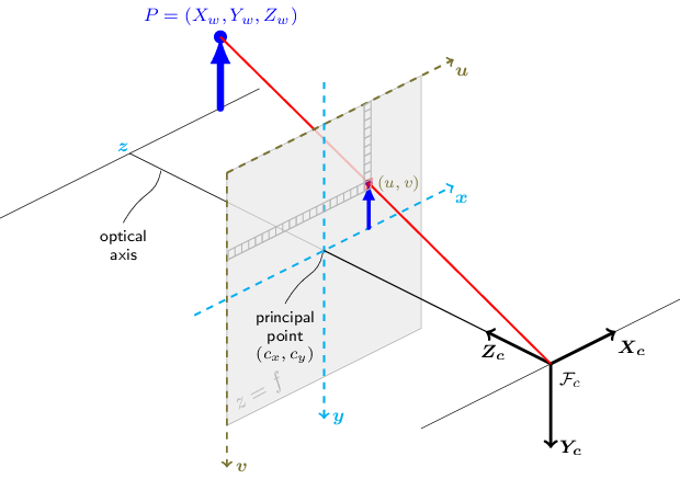
The functions in this section use a so-called pinhole camera model. The view of a scene
is obtained by projecting a scene’s 3D point into the image plane using a perspective
transformation which forms the corresponding pixel
. Both
and
are
represented in homogeneous coordinates, i.e. as 3D and 2D homogeneous vector respectively. You will
find a brief introduction to projective geometry, homogeneous vectors and homogeneous
transformations at the end of this section’s introduction. For more succinct notation, we often drop
the ‘homogeneous’ and say vector instead of homogeneous vector.
The distortion-free projective transformation given by a pinhole camera model is shown below.
where is a 3D point expressed with respect to the world coordinate system,
is a 2D pixel in the image plane,
is the camera intrinsic matrix,
and
are the rotation and translation that describe the change of coordinates from
world to camera coordinate systems (or camera frame) and
is the projective transformation’s
arbitrary scaling and not part of the camera model.
The camera intrinsic matrix (notation used as in Zhang2000 and also generally notated
as
) projects 3D points given in the camera coordinate system to 2D pixel coordinates, i.e.
The camera intrinsic matrix is composed of the focal lengths
and
, which are
expressed in pixel units, and the principal point
, that is usually close to the
image center:
and thus
The matrix of intrinsic parameters does not depend on the scene viewed. So, once estimated, it can be re-used as long as the focal length is fixed (in case of a zoom lens). Thus, if an image from the camera is scaled by a factor, all of these parameters need to be scaled (multiplied/divided, respectively) by the same factor.
The joint rotation-translation matrix is the matrix product of a projective
transformation and a homogeneous transformation. The 3-by-4 projective transformation maps 3D points
represented in camera coordinates to 2D points in the image plane and represented in normalized
camera coordinates
and
:
The homogeneous transformation is encoded by the extrinsic parameters and
and
represents the change of basis from world coordinate system
to the camera coordinate sytem
. Thus, given the representation of the point
in world coordinates,
, we
obtain
’s representation in the camera coordinate system,
, by
This homogeneous transformation is composed out of , a 3-by-3 rotation matrix, and
, a
3-by-1 translation vector:
and therefore
Combining the projective transformation and the homogeneous transformation, we obtain the projective transformation that maps 3D points in world coordinates into 2D points in the image plane and in normalized camera coordinates:
with and
. Putting the equations for instrincs and extrinsics together, we can write out
as
If , the transformation above is equivalent to the following,
with
The following figure illustrates the pinhole camera model.
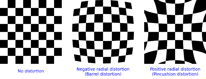
Real lenses usually have some distortion, mostly radial distortion, and slight tangential distortion. So, the above model is extended as:
where
with
and
if .
The distortion parameters are the radial coefficients ,
,
,
,
, and
,
and
are the tangential distortion coefficients, and
,
,
, and
,
are the thin prism distortion coefficients. Higher-order coefficients are not considered in OpenCV.
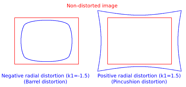
The next figures show two common types of radial distortion: barrel distortion
( monotonically decreasing)
and pincushion distortion (
monotonically increasing).
Radial distortion is always monotonic for real lenses,
and if the estimator produces a non-monotonic result,
this should be considered a calibration failure.
More generally, radial distortion must be monotonic and the distortion function must be bijective.
A failed estimation result may look deceptively good near the image center
but will work poorly in e.g. AR/SFM applications.
The optimization method used in OpenCV camera calibration does not include these constraints as
the framework does not support the required integer programming and polynomial inequalities.
See issue #15992 for additional information.
In some cases, the image sensor may be tilted in order to focus an oblique plane in front of the
camera (Scheimpflug principle). This can be useful for particle image velocimetry (PIV) or
triangulation with a laser fan. The tilt causes a perspective distortion of and
. This distortion can be modeled in the following way, see e.g. Louhichi07.
where
and the matrix is defined by two rotations with angular parameter
and
, respectively,
In the functions below the coefficients are passed or returned as
vector. That is, if the vector contains four elements, it means that . The distortion
coefficients do not depend on the scene viewed. Thus, they also belong to the intrinsic camera
parameters. And they remain the same regardless of the captured image resolution. If, for example, a
camera has been calibrated on images of 320 x 240 resolution, absolutely the same distortion
coefficients can be used for 640 x 480 images from the same camera while
,
,
, and
need to be scaled appropriately.
The functions below use the above model to do the following:
- Project 3D points to the image plane given intrinsic and extrinsic parameters.
- Compute extrinsic parameters given intrinsic parameters, a few 3D points, and their projections.
- Estimate intrinsic and extrinsic camera parameters from several views of a known calibration pattern (every view is described by several 3D-2D point correspondences).
- Estimate the relative position and orientation of the stereo camera “heads” and compute the rectification transformation that makes the camera optical axes parallel.
Homogeneous Coordinates
Homogeneous Coordinates are a system of coordinates that are used in projective geometry. Their use
allows to represent points at infinity by finite coordinates and simplifies formulas when compared
to the cartesian counterparts, e.g. they have the advantage that affine transformations can be
expressed as linear homogeneous transformation.
One obtains the homogeneous vector by appending a 1 along an n-dimensional cartesian
vector
e.g. for a 3D cartesian vector the mapping
is:
For the inverse mapping , one divides all elements of the homogeneous vector
by its last element, e.g. for a 3D homogeneous vector one gets its 2D cartesian counterpart by:
if .
Due to this mapping, all multiples , for
, of a homogeneous point represent
the same point
. An intuitive understanding of this property is that under a projective
transformation, all multiples of
are mapped to the same point. This is the physical
observation one does for pinhole cameras, as all points along a ray through the camera’s pinhole are
projected to the same image point, e.g. all points along the red ray in the image of the pinhole
camera model above would be mapped to the same image coordinate. This property is also the source
for the scale ambiguity s in the equation of the pinhole camera model.
As mentioned, by using homogeneous coordinates we can express any change of basis parameterized by
and
as a linear transformation, e.g. for the change of basis from coordinate system
0 to coordinate system 1 becomes:
Note:
- Many functions in this module take a camera intrinsic matrix as an input parameter. Although all functions assume the same structure of this parameter, they may name it differently. The parameter’s description, however, will be clear in that a camera intrinsic matrix with the structure shown above is required.
- A calibration sample for 3 cameras in a horizontal position can be found at opencv_source_code/samples/cpp/3calibration.cpp
- A calibration sample based on a sequence of images can be found at opencv_source_code/samples/cpp/calibration.cpp
- A calibration sample in order to do 3D reconstruction can be found at opencv_source_code/samples/cpp/build3dmodel.cpp
- A calibration example on stereo calibration can be found at opencv_source_code/samples/cpp/stereo_calib.cpp
- A calibration example on stereo matching can be found at opencv_source_code/samples/cpp/stereo_match.cpp
- (Python) A camera calibration sample can be found at opencv_source_code/samples/python/calibrate.py
Fisheye camera model
Definitions: Let P be a point in 3D of coordinates X in the world reference frame (stored in the matrix X) The coordinate vector of P in the camera reference frame is:
where R is the rotation matrix corresponding to the rotation vector om: R = rodrigues(om); call x, y and z the 3 coordinates of Xc:
The pinhole projection coordinates of P is [a; b] where
Fisheye distortion:
The distorted point coordinates are [x’; y’] where
Finally, conversion into pixel coordinates: The final pixel coordinates vector [u; v] where:
C API
Modules
Structs
Enums
cv::undistort mode
Constants
On-line Hand-Eye Calibration Andreff99
Hand-Eye Calibration Using Dual Quaternions Daniilidis98
Hand-eye Calibration Horaud95
Robot Sensor Calibration: Solving AX = XB on the Euclidean Group Park94
A New Technique for Fully Autonomous and Efficient 3D Robotics Hand/Eye Calibration Tsai89
Simultaneous robot-world and hand-eye calibration using dual-quaternions and kronecker product Li2010SimultaneousRA
Solving the robot-world/hand-eye calibration problem using the kronecker product Shah2013SolvingTR
for stereoCalibrate
use LU instead of SVD decomposition for solving. much faster but potentially less precise
use QR instead of SVD decomposition for solving. Faster but potentially less precise
7-point algorithm
8-point algorithm
least-median algorithm. 7-point algorithm is used.
RANSAC algorithm. It needs at least 15 points. 7-point algorithm is used.
least-median of squares algorithm
RANSAC algorithm
RHO algorithm
An Efficient Algebraic Solution to the Perspective-Three-Point Problem Ke17
Broken implementation. Using this flag will fallback to EPnP.
EPnP: Efficient Perspective-n-Point Camera Pose Estimation lepetit2009epnp
Infinitesimal Plane-Based Pose Estimation Collins14
Infinitesimal Plane-Based Pose Estimation Collins14
Used for count
Complete Solution Classification for the Perspective-Three-Point Problem gao2003complete
SQPnP: A Consistently Fast and Globally OptimalSolution to the Perspective-n-Point Problem Terzakis20
Broken implementation. Using this flag will fallback to EPnP.
USAC, accurate settings
USAC algorithm, default settings
USAC, fast settings
USAC, fundamental matrix 8 points
USAC, runs MAGSAC++
USAC, parallel version
USAC, sorted points, runs PROSAC
Traits
Levenberg-Marquardt solver. Starting with the specified vector of parameters it optimizes the target vector criteria “err” (finds local minima of each target vector component absolute value).
Class for computing stereo correspondence using the block matching algorithm, introduced and contributed to OpenCV by K. Konolige.
The base class for stereo correspondence algorithms.
The class implements the modified H. Hirschmuller algorithm HH08 that differs from the original one as follows:
Functions
Performs camera calibaration
Finds the camera intrinsic and extrinsic parameters from several views of a calibration pattern.
Finds the camera intrinsic and extrinsic parameters from several views of a calibration pattern.
Finds the camera intrinsic and extrinsic parameters from several views of a calibration pattern.
Finds the camera intrinsic and extrinsic parameters from several views of a calibration pattern.
Computes Hand-Eye calibration:
inline formula
Computes Robot-World/Hand-Eye calibration:
inline formula
andinline formula
Computes useful camera characteristics from the camera intrinsic matrix.
Combines two rotation-and-shift transformations.
For points in an image of a stereo pair, computes the corresponding epilines in the other image.
Converts points from homogeneous to Euclidean space.
Converts points to/from homogeneous coordinates.
Converts points from Euclidean to homogeneous space.
Refines coordinates of corresponding points.
Decompose an essential matrix to possible rotations and translation.
Decompose a homography matrix to rotation(s), translation(s) and plane normal(s).
Decomposes a projection matrix into a rotation matrix and a camera intrinsic matrix.
Distorts 2D points using fisheye model.
Renders the detected chessboard corners.
Draw axes of the world/object coordinate system from pose estimation. see also: solvePnP
Computes an optimal affine transformation between two 2D point sets.
Computes an optimal affine transformation between two 3D point sets.
Computes an optimal affine transformation between two 3D point sets.
Computes an optimal limited affine transformation with 4 degrees of freedom between two 2D point sets.
Estimates the sharpness of a detected chessboard.
Estimates new camera intrinsic matrix for undistortion or rectification.
Computes an optimal translation between two 3D point sets.
Filters homography decompositions based on additional information.
Filters off small noise blobs (speckles) in the disparity map
finds subpixel-accurate positions of the chessboard corners
Finds the positions of internal corners of the chessboard.
Finds the positions of internal corners of the chessboard using a sector based approach.
Finds the positions of internal corners of the chessboard using a sector based approach.
Finds centers in the grid of circles.
Finds centers in the grid of circles.
Calculates an essential matrix from the corresponding points in two images.
Calculates an essential matrix from the corresponding points in two images from potentially two different cameras.
Calculates an essential matrix from the corresponding points in two images from potentially two different cameras.
Calculates an essential matrix from the corresponding points in two images from potentially two different cameras.
Calculates an essential matrix from the corresponding points in two images from potentially two different cameras.
Calculates a fundamental matrix from the corresponding points in two images.
Calculates a fundamental matrix from the corresponding points in two images.
Calculates a fundamental matrix from the corresponding points in two images.
Finds a perspective transformation between two planes.
Finds a perspective transformation between two planes.
Computes undistortion and rectification maps for image transform by #remap. If D is empty zero distortion is used, if R or P is empty identity matrixes are used.
Projects points using fisheye model
Projects points using fisheye model
Performs stereo calibration
Stereo rectification for fisheye camera model
Transforms an image to compensate for fisheye lens distortion.
Undistorts 2D points using fisheye model
Returns the default new camera matrix.
Returns the new camera intrinsic matrix based on the free scaling parameter.
computes valid disparity ROI from the valid ROIs of the rectified images (that are returned by #stereoRectify)
Finds an initial camera intrinsic matrix from 3D-2D point correspondences.
Computes the projection and inverse-rectification transformation map. In essense, this is the inverse of #initUndistortRectifyMap to accomodate stereo-rectification of projectors (‘inverse-cameras’) in projector-camera pairs.
Computes the undistortion and rectification transformation map.
initializes maps for #remap for wide-angle
Computes partial derivatives of the matrix product for each multiplied matrix.
Projects 3D points to an image plane.
Recovers the relative camera rotation and the translation from an estimated essential matrix and the corresponding points in two images, using cheirality check. Returns the number of inliers that pass the check.
Recovers the relative camera rotation and the translation from an estimated essential matrix and the corresponding points in two images, using cheirality check. Returns the number of inliers that pass the check.
Recovers the relative camera rotation and the translation from an estimated essential matrix and the corresponding points in two images, using cheirality check. Returns the number of inliers that pass the check.
computes the rectification transformations for 3-head camera, where all the heads are on the same line.
Reprojects a disparity image to 3D space.
Converts a rotation matrix to a rotation vector or vice versa.
Computes an RQ decomposition of 3x3 matrices.
Calculates the Sampson Distance between two points.
Finds an object pose from 3 3D-2D point correspondences.
Finds an object pose from 3D-2D point correspondences. This function returns the rotation and the translation vectors that transform a 3D point expressed in the object coordinate frame to the camera coordinate frame, using different methods:
Finds an object pose from 3D-2D point correspondences. This function returns a list of all the possible solutions (a solution is a <rotation vector, translation vector> couple), depending on the number of input points and the chosen method:
Finds an object pose from 3D-2D point correspondences using the RANSAC scheme.
C++ default parameters
Refine a pose (the translation and the rotation that transform a 3D point expressed in the object coordinate frame to the camera coordinate frame) from a 3D-2D point correspondences and starting from an initial solution.
Refine a pose (the translation and the rotation that transform a 3D point expressed in the object coordinate frame to the camera coordinate frame) from a 3D-2D point correspondences and starting from an initial solution.
Calibrates a stereo camera set up. This function finds the intrinsic parameters for each of the two cameras and the extrinsic parameters between the two cameras.
Calibrates a stereo camera set up. This function finds the intrinsic parameters for each of the two cameras and the extrinsic parameters between the two cameras.
Computes rectification transforms for each head of a calibrated stereo camera.
Computes a rectification transform for an uncalibrated stereo camera.
This function reconstructs 3-dimensional points (in homogeneous coordinates) by using their observations with a stereo camera.
Transforms an image to compensate for lens distortion.
Computes the ideal point coordinates from the observed point coordinates.
Computes the ideal point coordinates from the observed point coordinates.
validates disparity using the left-right check. The matrix “cost” should be computed by the stereo correspondence algorithm